TIDT223 April 2021
2.4 Test Setup
The following images show the various test setups used along with a more in-depth look at the board and its setup.
Conducted testing introduction and initial testing:
CISPR 25 conducted test calls for a battery cable length of 200 mm–400 mm (about 8–16 inches), including the LISN connector. A 9-inch cable is used for the tests (see the following images).
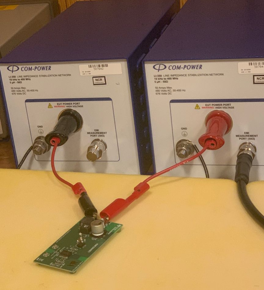 Figure 2-1 Conducted Test Setup
Passing cases with bottom side surface mount Y capacitor (Y cap).
The image shows two, size 1812 caps in series used to bridge the 8-mm primary to secondary gap. (581-1812HA101JAT1A Mouser / AVX MLCC - SMD/SMT 3KV 100 pF C0G 1812 5% HV) for 50 pF effective Y cap.
Also used higher value 220 pF surface mount Y caps for the effective 110-pF cap between primary and sec. 581-1825JA221KAT1A AVX / Mouser MLCC - SMD/SMT 4 KV 220 pF C0G 1825 10% Tol HV
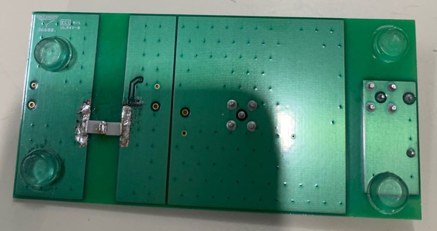 Figure 2-2 Bottom Side, Capacitor Bridge
Passing case with 220-pF top side through-hole Y cap added:
220-pF through-hole cap used TDK CC45SL3DD221JYNNA 2-kV rating, ceramic disc.
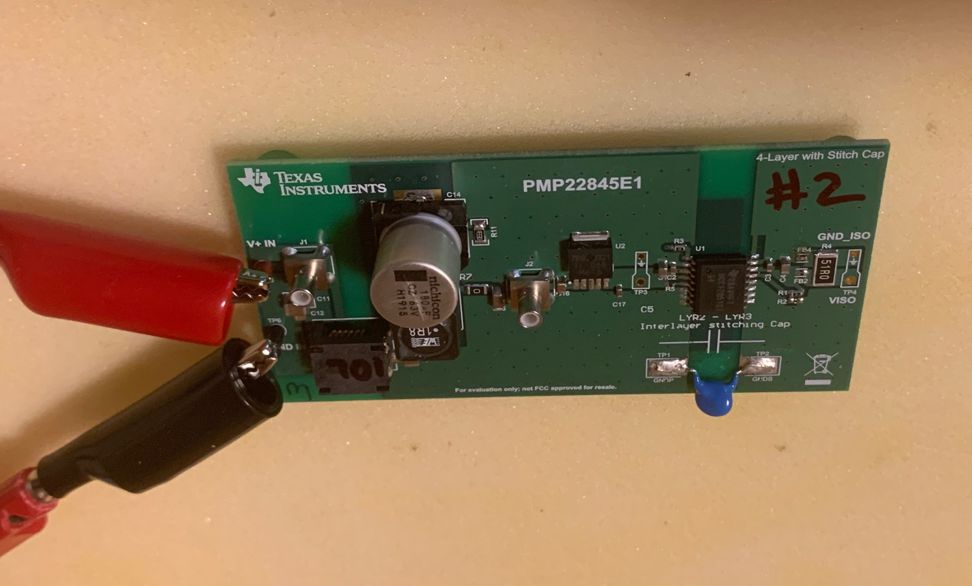 Figure 2-3 Top Side, Through Hole Y Cap Added
The following images show the EMI testing chamber and the different antenna configurations used.
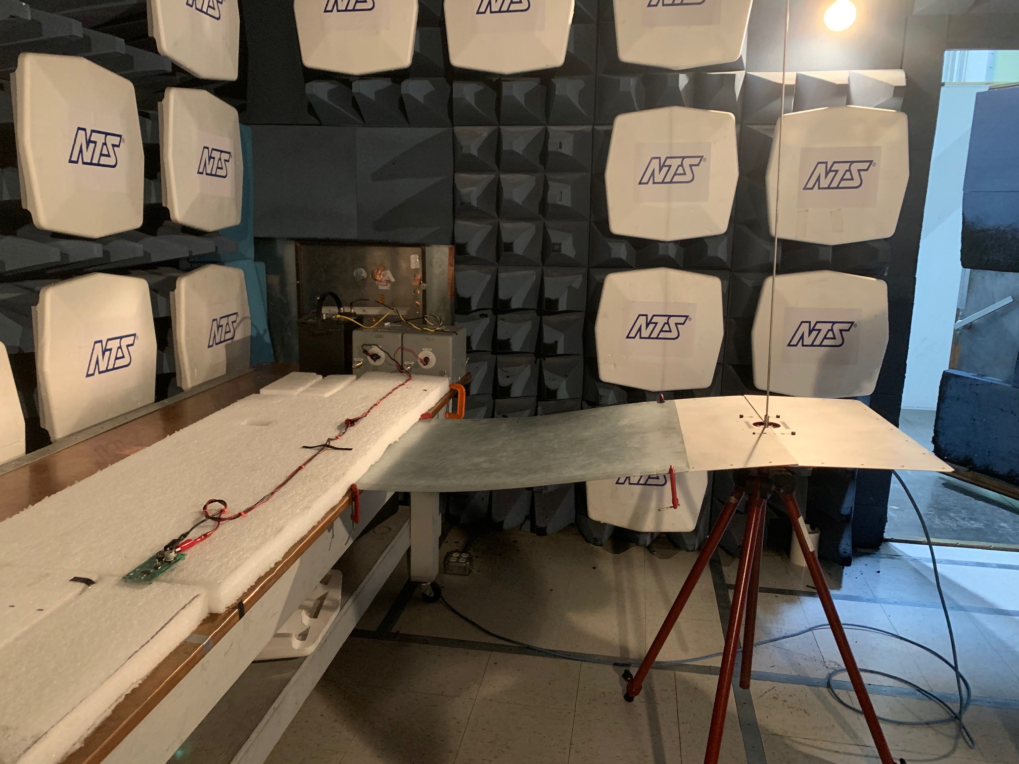 Figure 2-4 150 kHz–30 MHz Setup,
Vertical Monopole Antenna
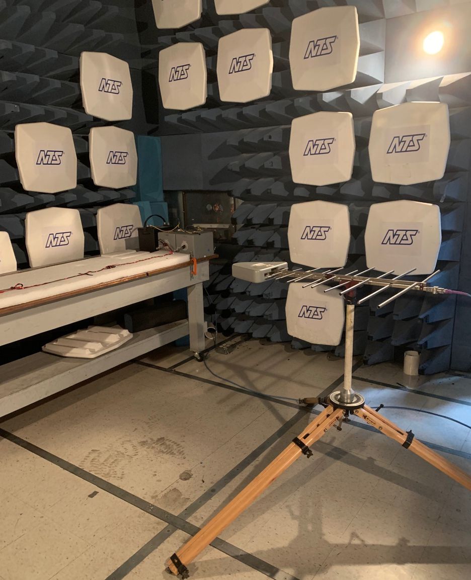 Figure 2-5 200 MHz –1000 MHz Setup,
Horizontal Log Periodic Antenna
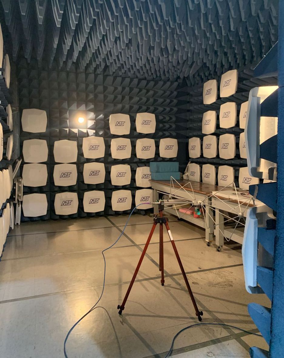 Figure 2-6 30 MHz –300 MHz Setup,
With Biconical Antenna Horizontal
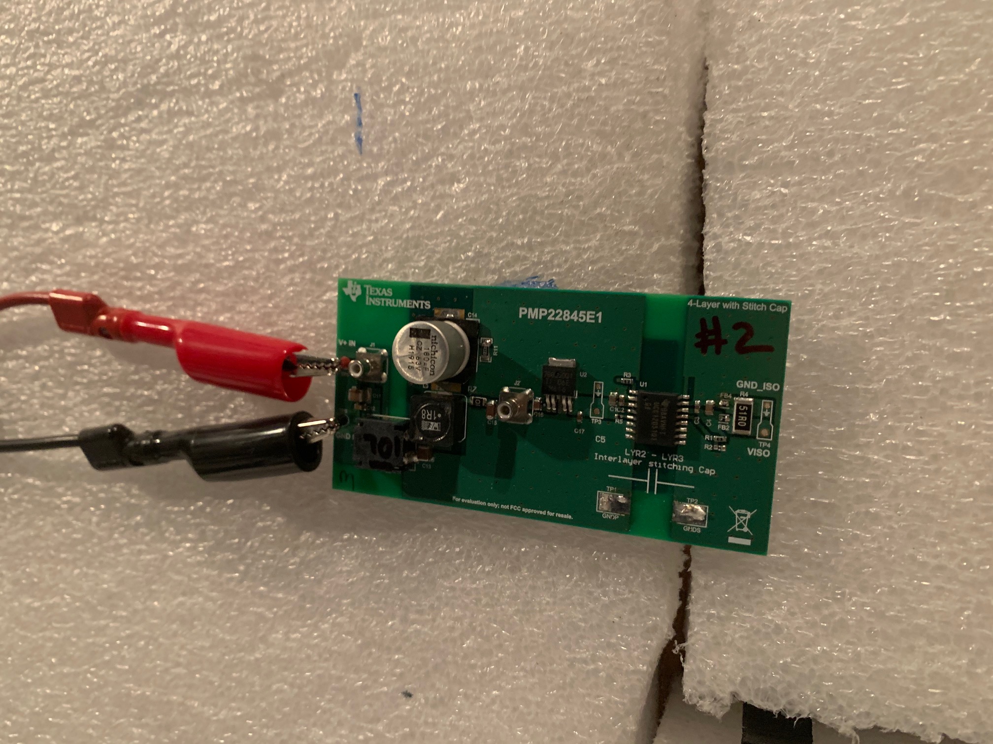 Figure 2-7 Unit Under Test: Top Side,
Version With Stitch Cap