TIDT388 February   2024


  1.   1
  2.   Description
  3.   Features
  4.   Applications
  5. 1Test Prerequisites
    1. 1.1 Voltage and Current Requirements
    2. 1.2 Required Equipment
    3. 1.3 Considerations
  6. 2Testing and Results
    1. 2.1 Efficiency, Power Loss, and Load Regulation Graphs
    2. 2.2 Thermal Images
    3. 2.3 Dimensions
  7. 3Waveforms
    1. 3.1 Switching
    2. 3.2 Output Voltage Ripple
    3. 3.3 Load Transient Response
    4. 3.4 Start-Up
    5. 3.5 Overcurrent Protection
    6. 3.6 Efficiency and Power Loss Comparison of Varying Solutions

Thermal Images

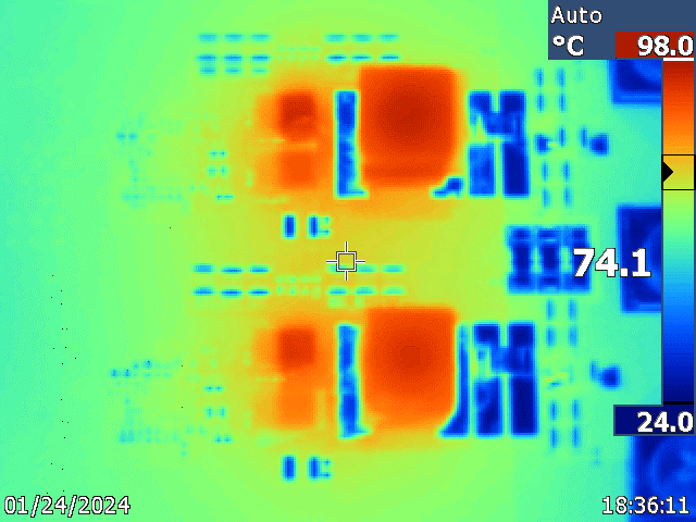
Figure 3-43 shows the buck converter thermal performance operating at 48V input and 30A load. The thermal test was conducted at room temperature with no airflow (natural convection), and the image was captured after thermal equilibrium was reached.
GUID-20240206-SS0I-7MTX-HPKW-RFTG7TSHTS4W-low.png
Natural convection (that is, no airflow); ambient at room temperature; thermal equilibrium reached
Figure 2-13 Thermal Image, 48V Input, 5V Output at 30A Load