TIDU312A May 2014 – November 2020
- Trademarks
- 1Introduction
- 2Software Overview
- 3Procedure for Running the Incremental Builds
- 4Test Results
- 5References
- 6Revision History
3.1.4.2 Step 1.2: Device Initialization, Main, and ISR Files
Note:
Do not make any changes to the source files –Only Inspect
- Open and inspect BridgelessPFC-DevInit_F2803x.c by double clicking on the filename in the project window. Note that system clock, peripheral clock prescale, and peripheral clock enables have been setup. Next, notice that the shared GPIO pins have been configured.
- Open and inspect BridgelessPFC -Main.c. Notice the call made to DeviceInit() function and other variable initialization. Also notice code for different incremental build options, the ISR intialization and the background for(;;) loop.
- Locate and inspect the following
code in the main file under initialization code specific for build 1. This is
where the PWMDRV_1ch_UpDwnCnt and ADCDRV_1CH blocks are connected
in the control flow.
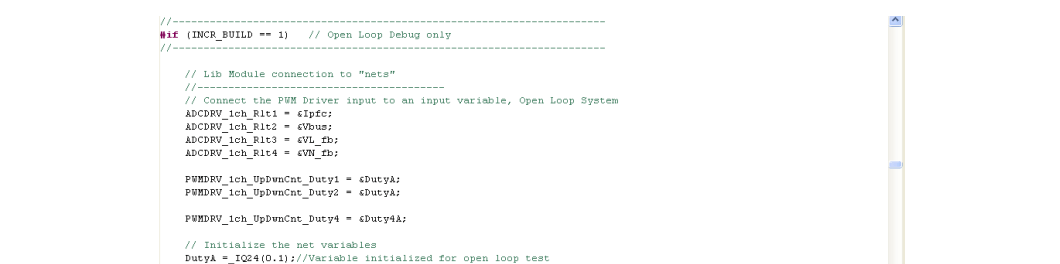
- Locate and inspect the following
code in the main file under initialization code. This is where the
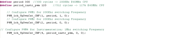
PWMDRV_1ch_UpDwnCnt block is configured and initialized. This is
common for all incremental builds. This PWM driver module inputs the total PWM
period value of 300 and internally calculates the period register value of 150.
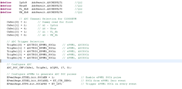
- Also
locate and inspect the following code in the main file under initialization
code. This is where the ADCDRV_1CH block is configured and initialized. This is
also common for all incremental builds.
- Open and inspect BridgelessPFC-DPL-ISR.asm. Notice the _DPL_Init and _DPL_ISR sections under build 1. This is where the PWM and ADC driver macro instantiation is done for initialization and runtime, respectively.