TIDUC07 March 2022
3.3.3 TMAG5170 In-Plane
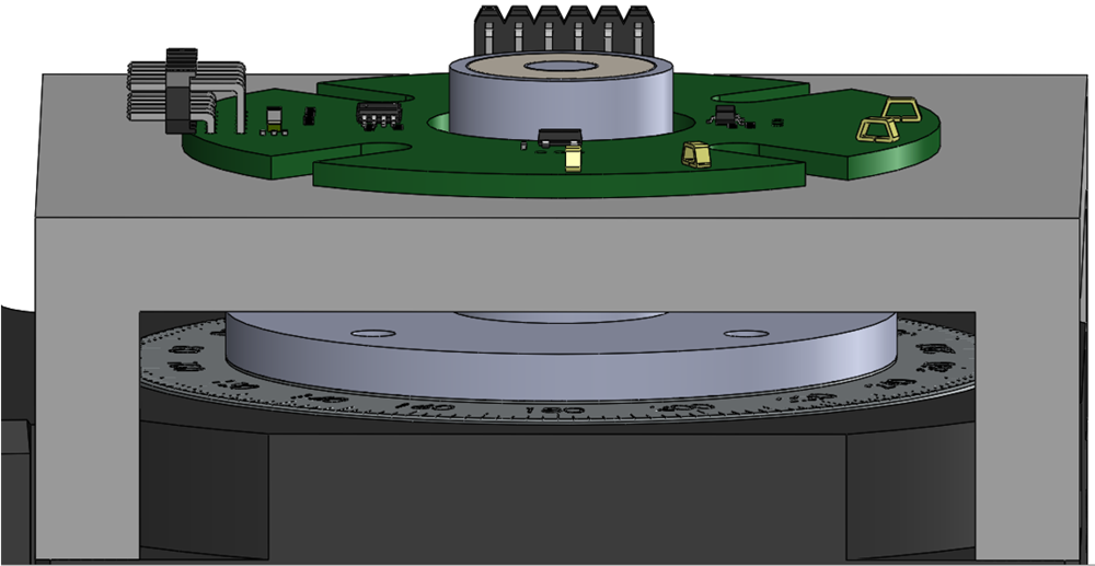
The in-plane alignment differs from the on-axis approach in that the sensor is placed coplanar to the magnet. This produces the smallest profile solution overall, but produces highly imbalanced input magnitudes.
Additionally, this alignment is the most susceptible to mechanical errors which is evident when examining the peak angle error. This position is very sensitive to eccentricity errors in the magnet rotation. Any magnet centering misalignment results with a changing airgap range. As demonstrated in In-Plane Magnitude vs Airgap Distance, small variations at this range have a significant impact on the magnitude of the magnetic field. It is particularly important when configuring a sensor in this position to exercise a great deal of care to achieve an exact mount for the magnet.
Additionally, at the outer edge of the magnet, the field vector direction is constantly changing as it wraps around to the opposing magnet pole. As a result tilt and alignment errors will result in phase error and changing input amplitudes.
 Figure 3-13 In-Plane Configuration
In-Plane Mechanical Angle Error shows the resulting pre-calibrated error captured for this alignment.
The angle error shown for the in-plane alignment appears quite extreme. With the assembly alignment errors for this test setup, a very dramatic angle error resulted. Even with this extreme of an error, it is still possible to apply a calibration to the end result to achieve accuracy below 0.1°.
| HARMONIC | αi | βi |
|---|---|---|
| 1 | 5.33 | 2.68 |
| 2 | –0.5 | –1.22 |
| 3 | –0.26 | 0.51 |
| 4 | 0.17 | 0.05 |
| 5 | –0.04 | –0.02 |
In-Plane Calibrated Angle Error shows the resulting error for both a direct arctangent calculation and for the CORDIC output after applying the harmonic data.