TIDUC07 March 2022
3.3.2 TMAG5170 On-Axis
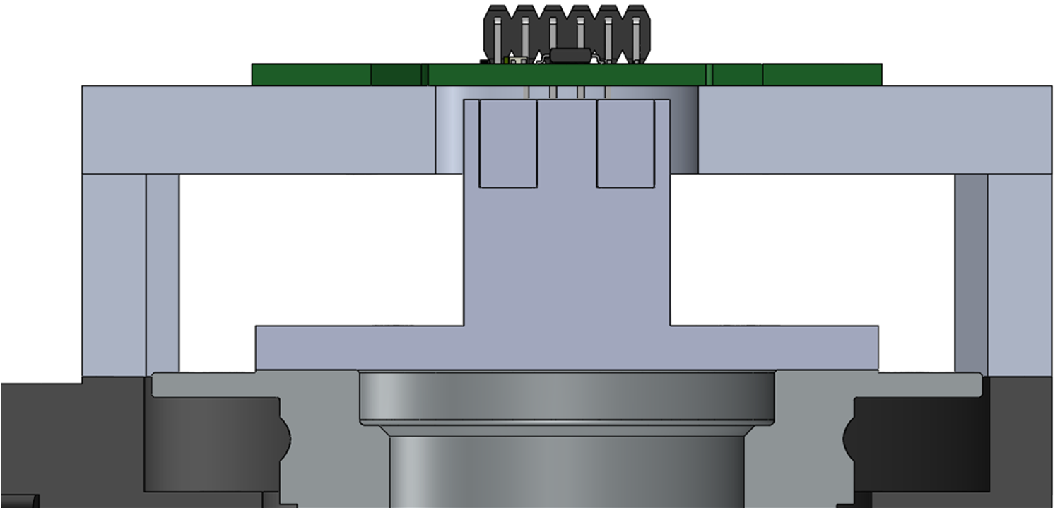
The on-axis alignment is the ideal case for measuring the angle of a magnetic field but requires additional area about the motor. Either the motor must be dual shaft or the end of the shaft is not available to drive the load. This results in the least compact solution size when implemented with any given motor. The impact of mechanical error is minimized in this orientation; however, which results in best uncalibrated results.
The mounting plate was configured to match the simulation results shown in Sensor Location.
Mechanical errors detailed in Calibration Methods are all present to some degree in each test case and the captured data reflects the result of these conditions after amplitude and offset corrections were applied.
The manual assembly and manufacturing tolerances of the entire setup resulted with mechanical errors which must be addressed. These alignment flaws demonstrated in the test results are crucial for the purpose of demonstrating the significance of alignment errors and how the calibration process can correct even large scale angle error. Strictly controlled manufacturing practices results with a reduced error from what is depicted for each case.
 Figure 3-10 On-Axis Configuration
On-Axis Mechanical Angle Error shows the resulting pre-calibrated error captured for this alignment.
Of all the alignment cases, on-axis is the most forgiving of mechanical alignment errors. Overall the field vector remains nearly parallel to the face of the magnet and therefore magnitude and phase shifts at the input are not as significant as is seen with the other alignment cases.
| HARMONIC | αi | βi |
|---|---|---|
| 1 | 0.42 | –0.73 |
| 2 | –0.35 | 0.07 |
| 3 | –0.01 | 0.06 |
| 4 | –0.02 | 0.01 |
On-Axis Calibrated Angle Error shows the resulting error for both a direct arctangent calculation and for the CORDIC output after applying the harmonic data.
It is worth noting here that the 0.25° resolution of the TMAG5170 CORDIC output does limit the measurement accuracy. To achieve the highest accuracy, directly calculate the arctangent result from the X and Y component outputs of the device. The benefit of the CORDIC output of TMAG5170 is that it reduces the burden for the microprocessor and can reduce overall measurement latency.