TIDUEZ2 March   2021


  1.   Description
  2.   Resources
  3.   Features
  4.   Applications
  5.   5
  6. 1System Description
    1. 1.1 Key System Specifications
  7. 2System Overview
    1. 2.1 Block Diagram
      1. 2.1.1 Obstacle Detection Application Software Block Diagram
    2. 2.2 Highlighted Products
      1. 2.2.1 AWR1843AOP Single-Chip Radar Solution
    3. 2.3 Design Considerations
      1. 2.3.1 System Design Theory
        1. 2.3.1.1 Usage Case Geometry and Sensor Considerations
        2. 2.3.1.2 Antenna Configuration
        3. 2.3.1.3 Processing Chain
      2. 2.3.2 Configuration Profile
  8. 3Hardware, Software, Testing Requirements, and Test Results
    1. 3.1 Required Hardware and Software
      1. 3.1.1 Hardware
      2. 3.1.2 Software and GUI
    2. 3.2 Testing and Results
      1. 3.2.1 Test Setup
      2. 3.2.2 Test Results
  9. 4Design and Documentation Support
    1. 4.1 Design Files
    2. 4.2 Software
    3. 4.3 Documentation Support
    4. 4.4 Support Resources
    5. 4.5 Trademarks

Configuration Profile

The example in the mmWave SDK distribution that represents this design lets users push the Radar configuration, using a Profile Configuration file (see Figure 2-8), over UART to the device.

The mmWave SDK user's guide (included in the mmWave SDK distribution) describes the semantics of the following commands in detail. The following sequence of commands represents the configuration choices described in previous sections representing the functionality of the ODS. The cfarCfg and dbscanCfg commands are described in more detail in the User's Guide included with the software release.
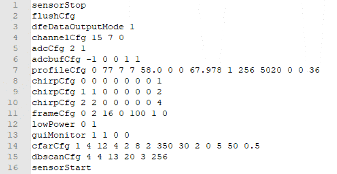
GUID-20210323-CA0I-ZMZD-LSW4-FWL1QXDFLSVQ-low.png Figure 2-8 ODS Profile Configuration