TIDUEZ8C december   2022  – june 2023


  1.   1
  2.   Description
  3.   Resources
  4.   Features
  5.   Applications
  6.   6
  7. 1System Description
    1. 1.1 Insulation Monitoring
    2. 1.2 Impact of Parasitic Isolation Capacitance
    3. 1.3 IEC 61557-8 Standard for Industrial Low-Voltage Distribution Systems
    4. 1.4 Key System Specifications
  8. 2System Overview
    1. 2.1 Block Diagram
    2. 2.2 Highlighted Products
      1. 2.2.1 TPSI2140
      2. 2.2.2 AMC3330
      3. 2.2.3 TPS7A24
      4. 2.2.4 REF2033
      5. 2.2.5 TLV6001
    3. 2.3 Design Considerations
      1. 2.3.1 Resistive Bridge
      2. 2.3.2 Isolated Analog Signal Chain
        1. 2.3.2.1 Differential to Single-Ended Conversion
        2. 2.3.2.2 High-Voltage Measurement
        3. 2.3.2.3 Signal Chain Error Analysis
      3. 2.3.3 Loss of PE Detection
      4. 2.3.4 Insulation Monitoring on AC Lines
      5. 2.3.5 PCB Layout Recommendations
  9. 3Hardware, Software, Testing Requirements, and Test Results
    1. 3.1 Hardware Requirements
      1. 3.1.1 Connectors
      2. 3.1.2 Default Jumper Configuration
      3. 3.1.3 Prerequisites
    2. 3.2 Software Requirements
    3. 3.3 Software
    4. 3.4 Test Setup
    5. 3.5 Test Results
  10. 4Design and Documentation Support
    1. 4.1 Design Files
      1. 4.1.1 Schematics
      2. 4.1.2 BOM
    2. 4.2 Documentation Support
    3. 4.3 Support Resources
    4. 4.4 Trademarks
  11. 5About the Author
  12. 6Revision History

Isolated Analog Signal Chain

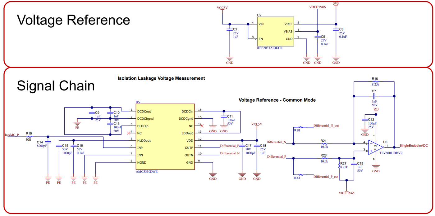
As a first part of the signal chain, the AMC3330 amplifies the measured voltage and provides the necessary isolation barrier, to protect the system from the high voltages. The ±2.05-V differential output signal of the AMC3330 is converted to a signal-ended 0-V to 3.3-V signal using the TLV6001 in a difference amplifier configuration, which is described in Section 2.3.2.1.

GUID-20210913-SS0I-ZTG8-RJN4-NWQNNZWBXVPN-low.svgFigure 2-7 Isolated Analog Signal Chain
GUID-20220401-SS0I-84FZ-16PJ-SCPBPQX90BVD-low.pngFigure 2-8 Schematic Isolated Analog Signal Chain + Reference

The output voltage of the differential to single-ended conversion is fed into a internal ADC of the C2000 microcontroller. The measured voltage at the ADC can be converted back to the insulation voltage using Equation 18:

Equation 18. Visolation=VinADC-VrefGaindiff2single×RinAMC+RstRinAMC×1GainAMC

where

  • Visolation is the actual isolation voltage monitored
  • VinADC is the voltage at the input of the ADC
  • Vref is the 1.65-V voltage reference coming from REF2033
  • Gaindiff2single is the differential-to-single ended gain set with the resistor divider, as explained in Section 2.3.2.1
  • GainAMC is the gain of the AMC3330 which is a fixed gain of 2.0
  • Rst is the switched resistive bridge equivalent resistance(RstP = RstN = Rst)
  • And RinAMC is the resistor that serves the scaled down isolation voltage to the input of the AMC3330