TIDUF01 November 2021 AWR2944 , IWR2944
2.4.10 Group Tracker
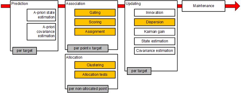
Real world radar targets (cars, pedestrians, and so forth) are presented to a tracking processing layer as a set of multiple reflection points. Those detection points form a group of correlated measurements with range, angle, SNR, and radial velocity. The group tracker, tracks a cluster of points (also known as group) in 2D over time based on a constant acceleration motion model. Figure 2-11 shows the main functional blocks of the group tracker algorithm. The subblocks shown in white are classical extended Kalman filter (EKF) operations. The subblocks shown in orange are additions to support multipoint grouping. More details about the group tracking algorithm are found in Group Tracker Parameter Tuning Guide for the 3D People Counting Demo.

Figure 2-11 Group Tracker Block Diagram
These parameter sets can be tweaked based on test results or as per scene requirement.
| SCENARIO | PARAMETER SETS | CLI COMMANDS | DESCRIPTION |
|---|---|---|---|
| 1 | Scenery Parameters | appSceneryParams | These define the dimensions of the physical space in which the tracker will operate. These also specify the radar sensor orientation and position. Any measurement points outside these boundary boxes are not used by the tracker. |
| 2 | Gating Parameters | appGatingParams | These determine the maximum volume and velocity of a tracked object and are used to associate measurement points with tracks that already exist. Points detected beyond the limits set by these parameters are not included in the set of points that make up the tracked object. |
| 3 | Allocation Parameters | appAllocParams | These are used to detect new tracks or people in the scene. When detected points are not associated with existing tracks, allocation parameters are used to cluster these remaining points and determine if that cluster qualifies as a person or target. |
| 4 | State Parameters | appStateParams | The state transition parameters determine the state of a tracking instance. Any tracking instance can be in one of three states: FREE, DETECT, or ACTIVE. |
| 5 |
Max Acceleration Parameters Max number of points Max number of tracks |
gtrack | Max acceleration parameters determine the maximum acceleration in the lateral, longitudinal, and vertical directions. |