TIDUF01 November   2021 AWR2944


  1.   Description
  2.   Resources
  3.   Features
  4.   Applications
  5.   5
  6. 1System Description
    1. 1.1 Why use Radar?
    2. 1.2 TI Corner Radar Design
    3. 1.3 Key System Specification
  7. 2System Overview
    1. 2.1 Block Diagram
    2. 2.2 Design Considerations
    3. 2.3 Highlighted Products
      1. 2.3.1 AWR2944 Single-Chip Radar Solution
      2. 2.3.2 AWR2944 Evaluation Module
    4. 2.4 System Design Theory
      1. 2.4.1  Antenna Configuration
      2. 2.4.2  Chirp Configuration and System Performance
      3. 2.4.3  Data Path
      4. 2.4.4  Chirp Timing
      5. 2.4.5  eDMA Configuration
      6. 2.4.6  Memory Allocation
      7. 2.4.7  DDMA
      8. 2.4.8  Empty Subband Based DDMA
      9. 2.4.9  RANSAC
      10. 2.4.10 Group Tracker
  8. 3Hardware, Software, Testing Requirements, and Test Results
    1. 3.1 Required Hardware and Software
      1. 3.1.1 Hardware
      2. 3.1.2 Software and GUI
    2. 3.2 Test Setup
    3. 3.3 Test Results
  9. 4Design and Documentation Support
    1. 4.1 Design Files
      1. 4.1.1 Schematics
      2. 4.1.2 BOM
    2. 4.2 Tools and Software
    3. 4.3 Documentation Support
    4. 4.4 Support Resources
    5. 4.5 Trademarks
  10. 5About the Author

Test Setup

The performance of the AWR2944 corner radar functionality was tested using the demonstration available in the TI Resource Explorer in the Automotive Toolbox: lab01027. The AWR2944BOOST EVM was used for the tests. Figure 3-3 illustrates a test setup scenario. AWR2944EVM is mounted on the rear end of the mid-size car
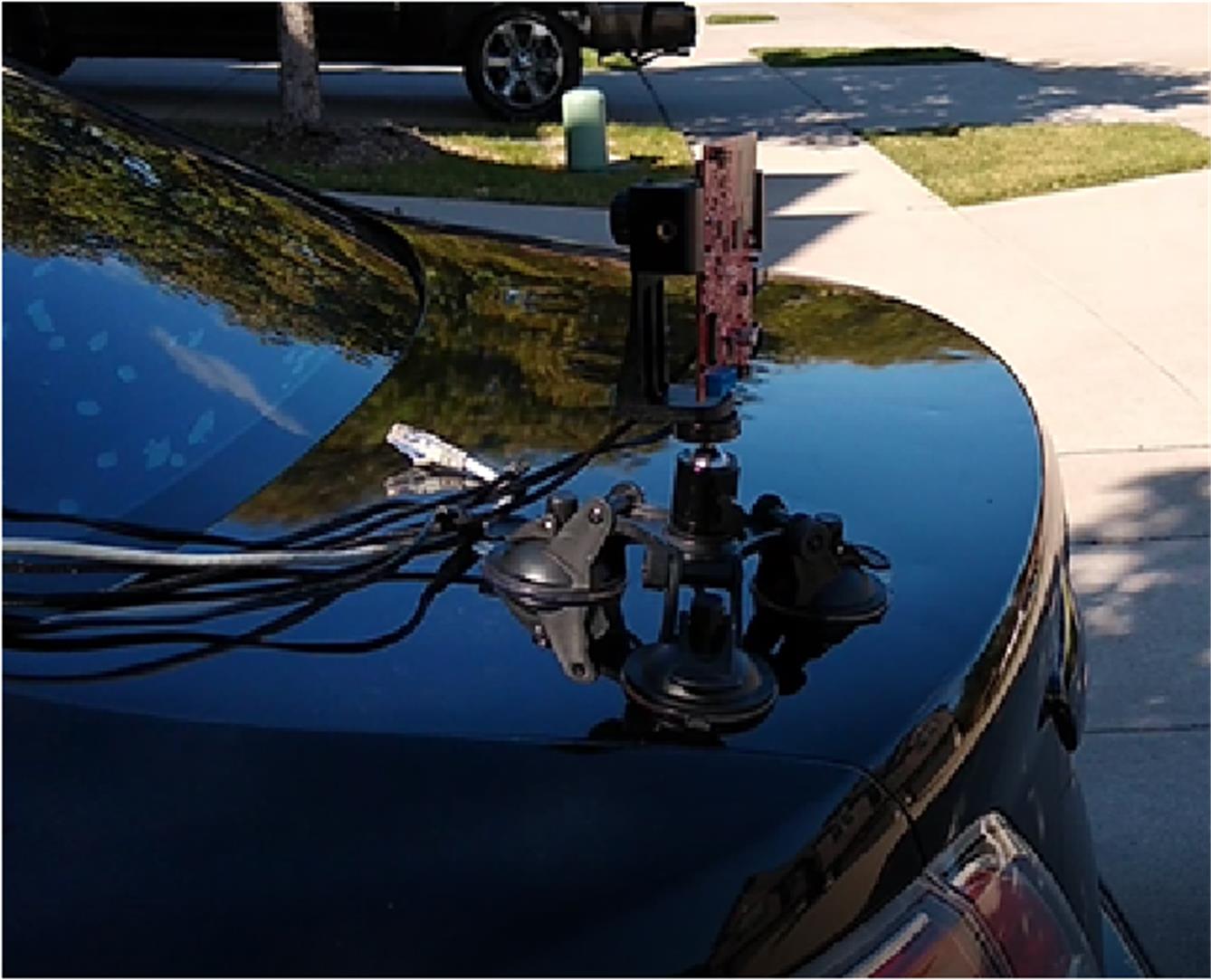

GUID-20211110-SS0I-Q2RN-4LBK-6KPMR8GSKMGQ-low.jpg

Figure 3-3 Test Setup