TIDUF25 june 2023 ADS131M08 , MSPM0G1507
- 1
- Description
- Resources
- Features
- Applications
- 6
- 1System Description
- 2System Overview
-
3System Design Theory
- 3.1 How to Implement Software for Metrology Testing
- 3.2 Clocking System
- 3.3 UART Setup for GUI Communication
- 3.4 Real-Time Clock (RTC)
- 3.5 LCD Controller in MSP430FR4131
- 3.6 Direct Memory Access (DMA)
- 3.7 ADC Setup
- 3.8 Foreground Process
- 3.9 Background Process
- 3.10 Software Function per_sample_dsp()
- 3.11 LED Pulse Generation
- 3.12 Phase Compensation
-
4Hardware, Software, Testing Requirements, and Test Results
- 4.1 Required Hardware and Software
- 4.2
Test Setup
- 4.2.1 Connecting the TIDA-010243 to the Metering Test Equipment
- 4.2.2 Power Supply Options and Jumper Settings
- 4.2.3 Electricity Meter Metrology Accuracy Testing
- 4.2.4 Viewing Metrology Readings and Calibration
- 4.2.5 Calibration and FLASH Settings for MSPM0+ MCU
- 4.2.6 Gain Calibration
- 4.2.7 Voltage and Current Gain Calibration
- 4.2.8 Active Power Gain Calibration
- 4.2.9 Offset Calibration
- 4.2.10 Phase Calibration
- 4.2.11 Software Code Example
- 4.3 Test Results
- 5Design and Documentation Support
- 6About the Author
4.2.1 Connecting the TIDA-010243 to the Metering Test Equipment
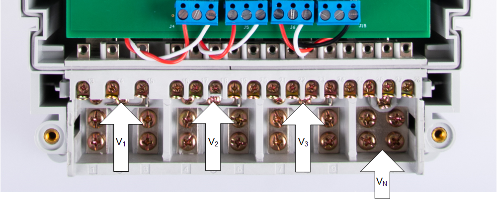
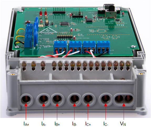
The design has support for 3-phase + Neutral configuration with current transformers (CT). AC voltages and currents can be applied to the board for testing purposes at these points:
- Terminal blocks "J1", "J2", and "J3", correspond to the line voltage connections for Phases A, B, and C, respectively. These terminal blocks have two positions.
- Terminal blocks "J4", "J5", and "J6" correspond to the current inputs after the sensors for Phases A, B, and C, respectively. These are three-position terminal blocks but only the leftmost and rightmost positions are used. The center position, which is connected to GND, is not connected to the CT. Select the applied current to the input of the CT so that the current does not exceed 100 A. In addition, before performing any test, verify that this terminal block is securely connected to both output leads of the CT.
- Terminal block "J15" corresponds to the current input after the sensor for the Neutral line. This terminal block is a three-position terminal block but only the leftmost and rightmost positions are used. The center position, which is connected to GND, is not connected to the CT. Select the applied current to the input of the CT so that the current does not exceed 100 A. In addition, before performing any test, verify that this terminal block is securely connected to both output leads of the CT.

Figure 4-2 Test Setup Configuration

Figure 4-3 Port Image