SBOA165F December 2020 – October 2022 INA186 , INA186-Q1 , INA190 , INA190-Q1 , INA199 , INA199-Q1 , INA210 , INA210-Q1 , INA211 , INA211-Q1 , INA212 , INA212-Q1 , INA213 , INA213-Q1 , INA214 , INA214-Q1 , INA215 , INA215-Q1 , INA225 , INA225-Q1 , INA240 , INA240-Q1 , INA301 , INA301-Q1
Current is a signal that can provide valuable insight into how a system is operating. Under defined conditions, the amount of current required to perform a task is consistent, making the current information a useful indicator to determine if the system is operating within expectations. There are multiple measurement methods and locations where current is measured to evaluate this informative signal.
Low-Side Sensing
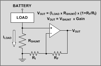
One current measurement location is in the return path to ground of a particular load or system. The device requirements for this location are minimal, requiring only an amplifier capable of handling a common-mode signal reaching down to ground. As shown in Figure 1-1, placing a small current sensing resistor (also called shunt resistor) in series with the system return path to ground develops a voltage across the resistor proportional to the current.
 Figure 1-1 Low-Side Current Sensing
Many types of amplifiers are able to accommodate this low-side capability with an input voltage range down to ground. Standard operational amplifiers, difference amplifiers, instrumentation amplifiers, and current sensing amplifiers are all capable of common-mode input ranges inclusive of ground.
Table 1-1 provides an overview on how each of these four amplifier types compare for current-sensing applications.
| VCM = 0 V | VCM > 0 V | Benefit | Disadvantage | |
|---|---|---|---|---|
| Operational amplifier | + | x | Low Cost | Accuracy, Low-Side |
| Difference amplifier | + | + | High-Side | Low Gain, Cost |
| Instrumentation amplifier | + | x | Accuracy, High Gain | Low-Side, Cost |
| Current sense amplifier | + | + | High-Side, High Gain, Accuracy | — |
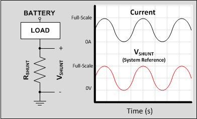
One of the drawbacks to low-side sensing is the loss of the direct connection to the system ground for the load being monitored. As shown in Figure 1-2, when current passes through the shunt resistor, the voltage developed across the component changes, causing the system reference to deviate from the ground potential of the monitored load. This varying reference connection can be problematic if the system is not able to accommodate the ground potential moving up and down proportionally to the system current.
 Figure 1-2 Varying Load Reference
In addition to the varying system ground, some fault conditions can be difficult to detect with a low-side measurement location. If a short-circuit condition results in current flowing through another path to ground other than through the shunt resistor, the event is not detectable by the low-side amplifier.
High-Side Sensing
Measuring current at the high-side of the load, or directly in series with the power rail being monitored and the remainder of the circuit, avoids both the varying system reference and alternate short-circuit path issues of low-side current measurements. The high-side location allows for measuring the entire system current, so any excess current through unintended paths is detected. Moving away from the low-side location eliminates the varying system ground due to the current induced shunt voltage.
A challenge associated with the high-side measurement location is that the amplifier must interface with large input voltage rails, such as high-voltage batteries. A typical signal chain path for measuring current is to amplify the voltage developed across a current sensing resistor, and direct that amplified signal to an analog-to-digital converter (ADC). The input range of an ADC (whether discrete or integrated within a microcontroller) is relatively small compared to the voltage rails being monitored in communication and industrial equipment. Common-mode voltage requirements can exceed 60 V, requiring an amplifier capable of input signals far exceeding the allowable input range for the low-voltage component.
Current sense amplifiers are dedicated amplifiers developed specifically to accommodate these high-voltage input levels, while keeping the lower voltage components following the amplifier within the linear input range and protecting them from overvoltage conditions.
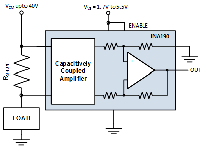
The INA190 current sense amplifier accommodates the requirement of monitoring high-voltage power rails and interfacing with lower voltage components, while being powered by a supply voltage as low as 1.7 V, as shown in Figure 1-3.
In the event the system is placed into a shutdown or sleep state, low-voltage supplies powering the ADCs, microcontrollers, and signal path amplifiers can potentially be turned off. However, batteries remain connected to the measurement circuitry even if the monitoring amplifiers are powered down. The INA190 features a capacitively coupled input stage that eliminates unnecessary current draw from the battery when disabled, or when the power supply is zero.
In always-on scenarios, the current sense amplifier input circuitry is specifically designed to accommodate the entire input range independent of the device supply voltage.
The INA190 can withstand the full 40-V input voltage at the input pins, regardless of whether a supply voltage is present or not, while drawing very little current from the supply, and without being damaged.
 Figure 1-3 INA190: Dedicated Current-Sensing Amplifier
Alternate Device Recommendations
For applications that need the performance of the INA190 in a smaller package with lower voltage enable thresholds, the INA191 is offered in a small 0.96-mm2 chip-scale package. For applications with voltages up to 110 V and fast settling requirements, using the INA296B with high bandwidth is a great choice for a dedicated current sense amplifier. The INA241B also provides an input common-mode voltage range reaching up to 110 V and features enhanced PWM rejection circuitry for applications with large common-mode input voltage transitions, such as motor control and switching power supplies. The INA301 current sense amplifier features an onboard comparator to perform overcurrent detection on chip.
| Device | Optimized Parameter | Performance Trade-Off |
|---|---|---|
| INA296B | High VCM: –4 V to +110 V, Bandwidth, Fast settling time | IQ, IB, Package: SOT-23 |
| INA191 | Small Size, 1.8-V Enable, Accuracy | Package: WCSP-6 |
| INA241B | High VCM: –4 V to +110 V, Enhanced PWM Rejection | IQ, IB, Package: SOT-23 |
| INA301 | Signal Bandwidth, Onboard Comparator | IQ, IB, Package: MSOP-8 |