SCDA032 January 2021 TMUX1108 , TMUX1111 , TMUX6208 , TMUX6211 , TMUX7219
Application Brief
Introduction
Continuous-wave Doppler (CWD) can determine blood-flow velocity through major arteries and veins around the body by sending and receiving sound waves that bounce off solid objects, including blood cells. The movement of blood cells causes a change in the frequency of the reflected sound waves; that’s the Doppler effect.
Filtering and extracting the CWD signal can be difficult as the frequencies and amplitudes can vary due to velocity and direction of blood flow, unwanted harmonics, and noise.
This application brief describes two ways to overcome these challenges by incorporating multiplexers around operational amplifiers in the CWD signal path that can help isolate, filter, or configure the desired signal, resulting in a better overall real-time ultrasound imaging.
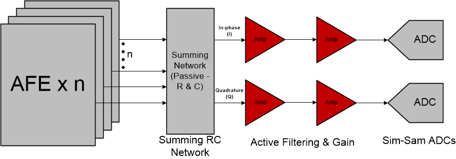
Ultrasound systems typically extract a received CWD signal at the low-noise amplifier output within the analog front end and is mixed to base band in-phase (I) and quadrature (Q) frequencies for processing.
Figure 1-1 shows the summing, amplifying. and filtering of these I and Q signals before they reach the ADC.
 Figure 1-1 The CWD Receive Signal Chain
for Ultrasound
Figure 1-1 The CWD Receive Signal Chain
for UltrasoundSwitching Between Different Gain Values
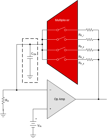
One way to configure the CWD signal is to control the amplification of the signal by creating a discrete programmable gain amplifier through a multiplexer, resistors, and an operational amplifier. The multiplexer switches between different resistance values, which in turn, allows for different gain values from the same operational amplifier.
In Figure 1-2, incorporating a 1-to-1 four-channel multiplexer with ±18-V signal capabilities, such as the TMUX6211, with feedback resistors can create a discrete programmable gain amplifier.
 Figure 1-2 Circuit Model of a Basic Discrete Programmable Gain Amplifier
Filtering with Multiplexers
Another way to configure the CWD signal is to filter the desired signal before reaching the ADC. The extracted CWD signal can include noise that stem from electronic interference, harmonics, and transmit beam artifacts.
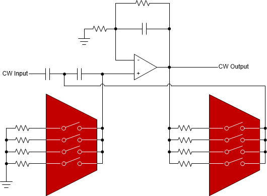
To maintain signal integrity, a band pass filter can be used to obtain for the desired signal and remove any undesired noise or interference. For example, a Sallen and Key filter can be created with two resistors and a single non-inverting operational amplifier.
As shown in Figure 1-3, adding multiplexers to the Sallen and Key filter design allow for a greater number of resistance values to switch between, thus allowing for operational amplifier to dynamically change the cut-off frequency.
Summary
Dynamically maintaining signal integrity is critical in the CWD receive path for ultrasound. Multiplexers can help isolate, filter or configure the active filtering and gain stage of the CWD receive path.
TI multiplexers can add flexibility to the gain and filtering stages, allowing configurability and have more precise data conversions to the ADC, resulting in better real-time imaging.
Additional resources: Choosing the Right Multiplexer for a Discrete Programmable Gain Amplifiers (PGA) application brief.
 Figure 1-3 Circuit Model of a Basic
Sallen and Key Filter with Multiplexers
Figure 1-3 Circuit Model of a Basic
Sallen and Key Filter with Multiplexers| Device | Configuration | Channels | Voltage Supply | On-Resistance (Typical) |
|---|---|---|---|---|
| TMUX6211 | 1-to-1 | 4 |
4.5 V to 36 V ±4.5 V to ± 18 V |
2 Ω |
| TMUX1111 | 1-to-1 | 4 | 1.08 V to 5.5 V | 2 Ω |
| TMUX7219 | 2-to-1 | 1 |
4.5 V to 44 V ±4.5 V to ± 22 V |
2 Ω |
| TMUX6208 | 8-to-1 | 1 |
4.5 V to 36 V ±4.5 V to ± 18 V |
4 Ω |
| TMUX1108 | 8-to-1 | 1 |
1.08 V to 5.5 V ±2.5 V |
2.5 Ω |