SLLS154C March 1993 – February 2024 SN75ALS1177 , SN75ALS1178
PRODUCTION DATA
- 1
- 1 Features
- 2 Applications
- 3 Description
- 4 Pin Configuration and Functions
- 5 Specifications
- 6 Parameter Measurement Information
- 7 Detailed Description
- 8 Device and Documentation Support
- 9 Revision History
- 10Mechanical, Packaging, and Orderable Information
Package Options
Refer to the PDF data sheet for device specific package drawings
Mechanical Data (Package|Pins)
- NS|16
- N|16
Thermal pad, mechanical data (Package|Pins)
Orderable Information
3 Description
The SN75ALS1177 and SN75ALS1178 dual differential drivers and receivers are integrated circuits designed for bidirectional data communication on multipoint bus transmission lines. The devices are designed for balanced transmission lines, and meet standards TIA/EIA-422-B and TIA/EIA-485-A.
The SN75ALS1177 combines dual 3-state differential line drivers and dual 3-state differential input line receivers, both of which operate from a single 5V power supply. The drivers and receivers have active-high and active-low enables, respectively, which can be externally connected together to function as direction control. The SN75ALS1178 drivers each have an individual active-high enable. Fail-safe design ensures that when the receiver inputs are open, the receiver outputs are always high.
The SN75ALS1177 and SN75ALS1178 are characterized for operation from 0°C to 70°C.
| PART NUMBER | PACKAGE(1) | PACKAGE SIZE(2) |
|---|---|---|
| SN75ALS1177 SN75ALS1178 | SOP (NS, 16) | 10.2mm × 7.8mm |
| PDIP (N, 16) | 19.3mm × 9.4mm |
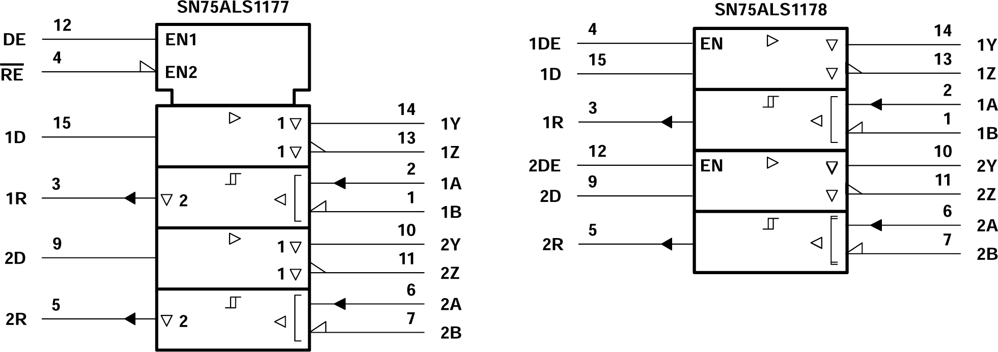
 Logic Symbol(1)
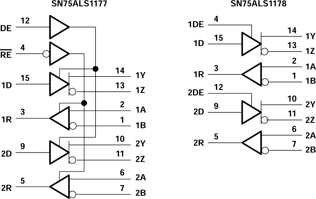
 Logic Diagram (Positive Logic)