JAJSQ22J september   2011  – may 2023 LMK00301

PRODUCTION DATA  

  1.   1
  2. 特長
  3. アプリケーション
  4. 概要
  5. Revision History
  6. Device Comparison
  7. Pin Configuration and Functions
  8. Specifications
    1. 7.1 Absolute Maximum Ratings
    2. 7.2 ESD Ratings
    3. 7.3 Recommended Operating Conditions
    4. 7.4 Thermal Information
    5. 7.5 Electrical Characteristics
    6. 7.6 Typical Characteristics
  9. Parameter Measurement Information
    1. 8.1 Differential Voltage Measurement Terminology
  10. Detailed Description
    1. 9.1 Overview
    2. 9.2 Functional Block Diagram
    3. 9.3 Feature Description
      1. 9.3.1 VCC and VCCO Power Supplies
    4. 9.4 Device Functional Modes
      1. 9.4.1 Clock Inputs
      2. 9.4.2 Clock Outputs
        1. 9.4.2.1 Reference Output
  11. 10Application and Implementation
    1. 10.1 Application Information
    2. 10.2 Typical Application
      1. 10.2.1 Design Requirements
        1. 10.2.1.1 Driving the Clock Inputs
        2. 10.2.1.2 Crystal Interface
      2. 10.2.2 Detailed Design Procedure
        1. 10.2.2.1 Termination and Use of Clock Drivers
          1. 10.2.2.1.1 Termination for DC Coupled Differential Operation
          2. 10.2.2.1.2 Termination for AC Coupled Differential Operation
          3. 10.2.2.1.3 Termination for Single-Ended Operation
      3. 10.2.3 Application Curves
  12. 11Power Supply Recommendations
    1. 11.1 Power Supply Sequencing
    2. 11.2 Current Consumption and Power Dissipation Calculations
      1. 11.2.1 Power Dissipation Example #1: Separate VCC and VCCO Supplies with Unused Outputs
      2. 11.2.2 Power Dissipation Example #2: Worst-Case Dissipation
    3. 11.3 Power Supply Bypassing
      1. 11.3.1 Power Supply Ripple Rejection
    4. 11.4 Thermal Management
  13. 12Layout
    1. 12.1 Layout Guidelines
    2. 12.2 Layout Example
  14. 13Device and Documentation Support
    1. 13.1 Documentation Support
      1. 13.1.1 Related Documentation
    2. 13.2 ドキュメントの更新通知を受け取る方法
    3. 13.3 サポート・リソース
    4. 13.4 Trademarks
    5. 13.5 静電気放電に関する注意事項
    6. 13.6 用語集
  15. 14Mechanical, Packaging, and Orderable Information

パッケージ・オプション

メカニカル・データ(パッケージ|ピン)
サーマルパッド・メカニカル・データ
発注情報

概要

LMK00301 デバイスは 3GHz、10 出力の差動ファンアウト・バッファで、高周波数、低ジッタのクロック / データ分配およびレベル変換を目的としています。入力クロックは 2 つの汎用入力、または 1 つの水晶振動子入力から選択できます。選択された入力クロックは 2 つのバンクに分配され、それぞれのバンクには 5 つの差動出力と 1 つの LVCMOS 出力があります。差動出力バンクは両方とも、LVPECL、LVDS、HCSL ドライバとして相互に構成するか、ディスエーブルにできます。LVCMOS 出力には同期イネーブル入力があり、イネーブルまたはディスエーブル時にラント (微小) パルスなしの動作を実現できます。LMK00301 は 3.3V のコア電源、および 3 つの独立した 3.3V または 2.5V の出力電源で動作します。

LMK00301 は高性能、多用途、優れた電力効率から、固定出力のバッファ・デバイスの代替品として理想的で、システムのタイミング・マージンを拡大できます。LMK00301 には、コア電源ドメインと出力電源ドメインの間に電源シーケンス要件がない設計スピン LMK00301A があります。

パッケージ情報 (1)
部品番号 パッケージ パッケージ・サイズ (公称)
LMK00301 (2) WQFN (48) 7.00mm × 7.00mm
利用可能なすべてのパッケージについては、このデータシートの末尾にある注文情報を参照してください。
LMK00301A は、データシートの末尾にある注文可能な付録として利用可能なデザイン・スピンです。
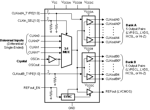
GUID-E01E603D-9609-4C67-BBA1-B4DE5DA10FC5-low.gif機能ブロック図