DLPU127 December   2023 DLP470NE , DLP480RE , DLP550HE , DLP550JE , DLP650LE , DLP650NE , DLP670RE , DLP780NE , DLP800RE , DLPC4430


  1.   1
  2.   Description
  3.   Get Started
  4.   Features
  5.   Applications
  6.   6
  7. 1Evaluation Module Overview
    1. 1.1 Introduction
    2. 1.2 Kit Contents
    3. 1.3 Specification
    4. 1.4 Device Information
    5. 1.5 Other Items Needed for Operation
  8. 2Software
    1. 2.1 Connecting the DMD EVM to the DLPC4430EVM
    2. 2.2 Quick Start
      1. 2.2.1 Downloading the Software
      2. 2.2.2 Powering-up the DLPC4430EVM and Preparing for the DLPC4430EVM to be Programmed
      3. 2.2.3 Programming the DLPC4430EVM and Displaying a SPLASH Image
      4. 2.2.4 JTAG Flash Programming
      5. 2.2.5 Flash Device Parameters
      6. 2.2.6 Troubleshooting
  9. 3Hardware
    1. 3.1 Connections
      1. 3.1.1 DLPC4430EVM Connections
        1. 3.1.1.1 DLPC4430EVM Connectors
        2. 3.1.1.2 DLPC4430EVM Test Points
      2. 3.1.2 DLP780NEEVM/DLP800REEVM Connections
        1. 3.1.2.1 DLP780NEEVM/DLP800REEVM Connectors
        2. 3.1.2.2 DLP780NEEVM/DLP800REEVM Test Points
      3. 3.1.3 DLP470NEEVM/DLP480REEVM Connections
        1. 3.1.3.1 DLP470NEEVM/DLP480REEVM Connectors
        2. 3.1.3.2 DLP470NEEVM/DLP480REEVM Test Points
      4. 3.1.4 DLP550HEEVM/DLP550JEEVM/DLP650LEEVM Connections
        1. 3.1.4.1 DLP550HEEVM/DLP550JEEVM/DLP650LEEVM Connectors
        2. 3.1.4.2 DLP550HEEVM/DLP550JEEVM/DLP650LEEVM Test Points
      5. 3.1.5 DLP650NEEVM/DLP670REEVM Connections
        1. 3.1.5.1 DLP650NEEVM/DLP670REEVM Connectors
        2. 3.1.5.2 DLP650NEEVM/DLP670REEVM Test Points
    2. 3.2 Power Supply Requirements
      1. 3.2.1 External Power Supply Requirements
  10. 4Hardware Design Files
    1. 4.1 Schematics
    2. 4.2 PCB Layouts
    3. 4.3 Bill of Materials (BOM)
  11. 5Additional Information
    1. 5.1 If You Need Assistance
    2. 5.2 Caution Labels
    3.     Trademarks
  12. 6Related Documentation

Kit Contents

The DMD EVMs found in Table 4-5 and DLPC4430EVM are designed to be used in pairs. The DMD EVMs cannot operated with the Controller EVM, DLPC4430EVM.

The DMD EVMs have a board-mounted connector that mates with to the DLPC4430EVM controller board. DLPC4430EVM includes all circuitry required to drive the DMD EVM.

The DLPC4430EVM includes one DLPC4430 controller, two DLPA100s which serve as the power management and motor drivers, and other system circuitry such as the parallel receiver and system fan control.

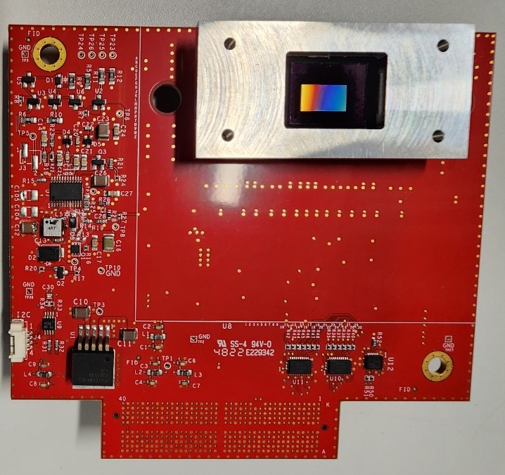
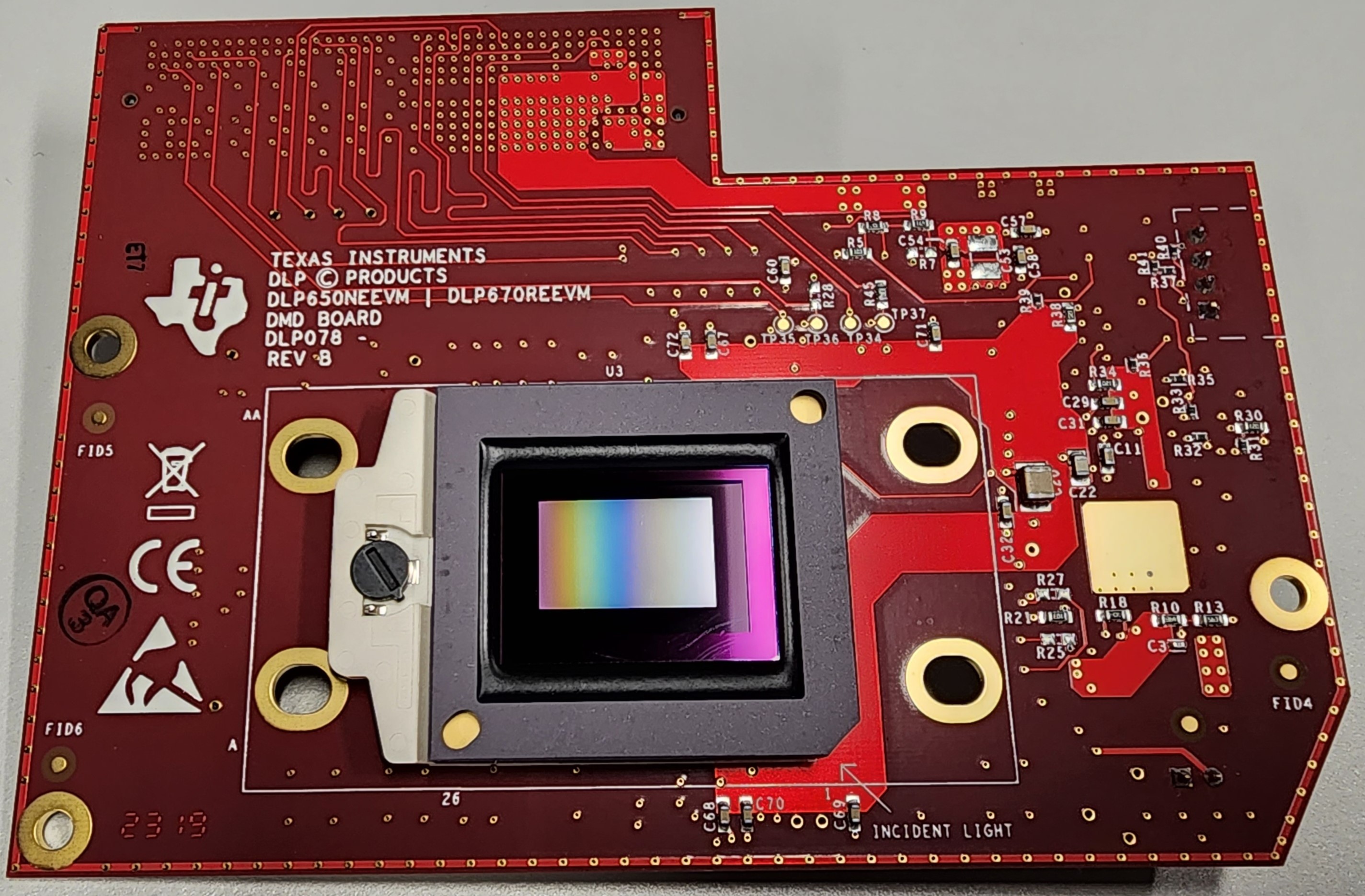
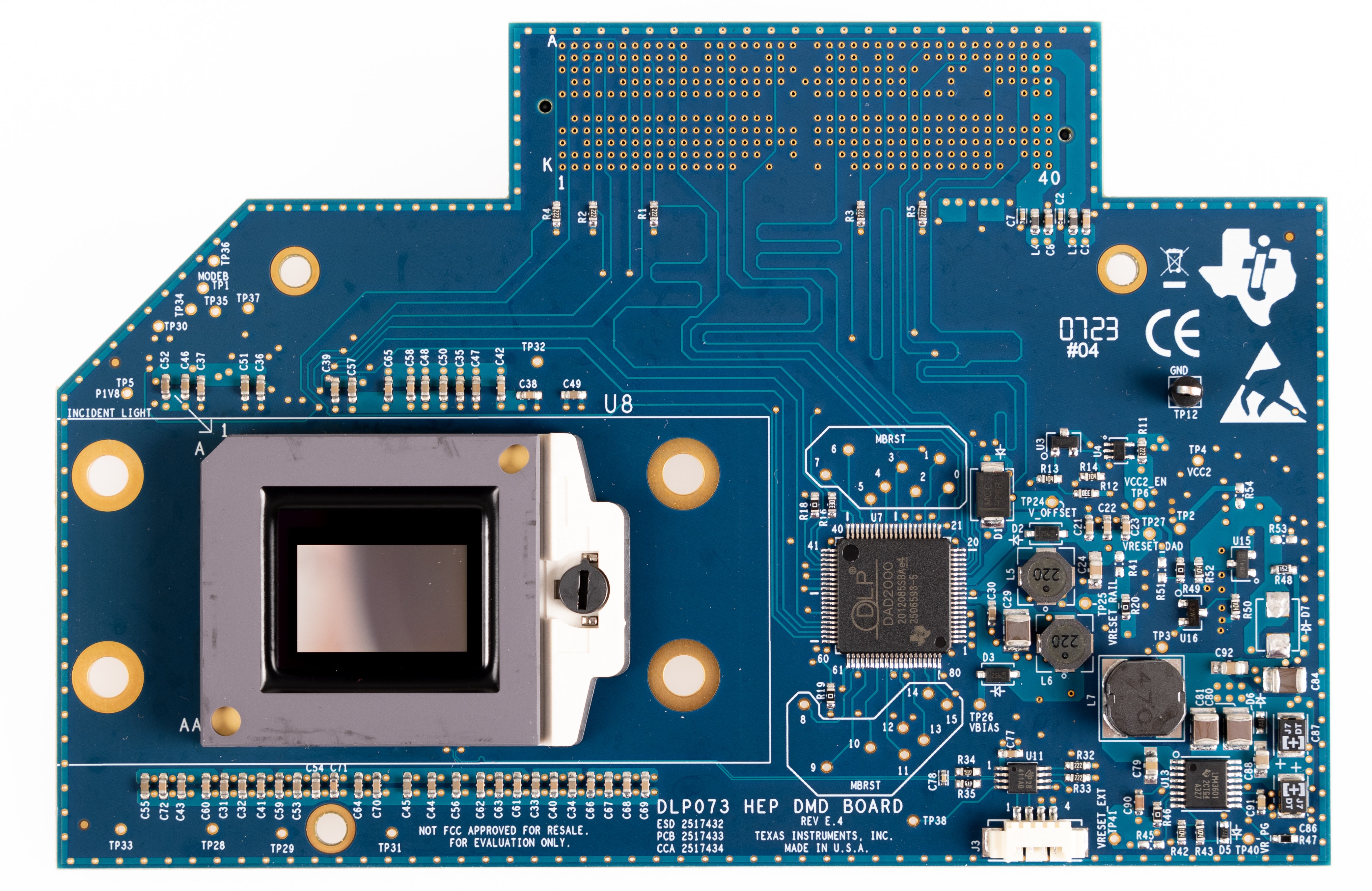
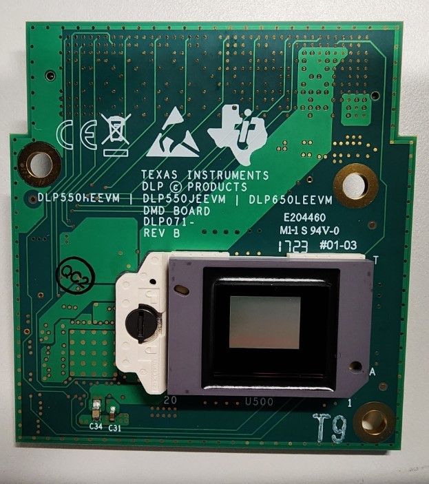
The DLPC4430EVM can be programmed with any firmware which is available on the DLPC4430 product page. This firmware allows the DLPC4430EVM to drive the desired display chip. Figure 2-1, Figure 2-2, Figure 2-3, Figure 2-3, and Figure 2-3 show the top side of each EVM.
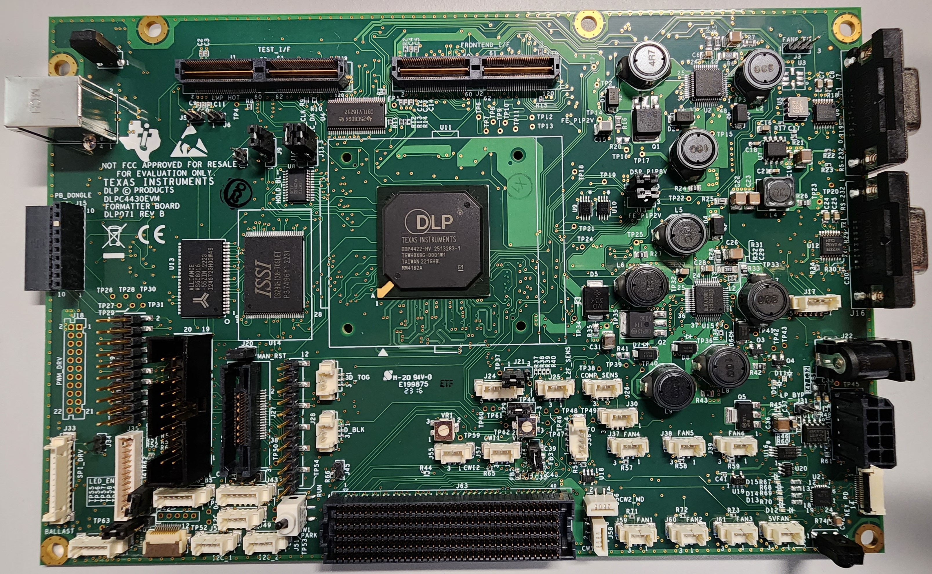
GUID-6329231D-E584-4B67-B630-90ACBB158A9A-low.jpgFigure 1-1 DLPC4430EVM
GUID-B73FAA97-4560-4344-917A-285F689242F1-low.jpgFigure 1-3 DLP470NEEVM/DLP480REEVM
GUID-20231218-SS0I-1NZH-FDWQ-QMVXS7XVPWNS-low.jpgFigure 1-5 DLP650NEEVM/DLP670REEVM
GUID-D07BC378-CD63-4688-A0D1-F81EF6FBB770-low.jpgFigure 1-2 DLP780NEEVM/DLP800REEVM
GUID-B03166A1-7684-4D17-9C89-5CA603C52166-low.jpgFigure 1-4 DLP550HEEVM/DLP550JEEVM/DLP650LEEVM