DLPU127 December 2023 DLP470NE , DLP480RE , DLP550HE , DLP550JE , DLP650LE , DLP650NE , DLP670RE , DLP780NE , DLP800RE , DLPC4430
- 1
- Description
- Get Started
- Features
- Applications
- 6
- 1Evaluation Module Overview
- 2Software
- 3Hardware
- 4Hardware Design Files
- 5Additional Information
- 6Related Documentation
2.2.2 Powering-up the DLPC4430EVM and Preparing for the DLPC4430EVM to be Programmed
Before powering up the EVM, make sure the included DLPC4430EVM jumpers are in the correct positions. The jumper locations are listed in Table 3-1 .
| Jumper | Description (Bold Indicates Default Position) |
|---|---|
| J9 - Red LED enable or Lamp Ballast | Pins 1, 2 connected Red LED Enable Pins 2,3 connected Lamp Mode |
| J10 - Daughter Card I2C Clock | Pins 1, 2 connected I2C to SCL1 Pins 2,3 connected I2C to SCL0 |
| J11 - Daughter Card I2C Data | Pins 1, 2 connected I2C to SDA1 Pins 2,3 connected I2C to SDA0 |
| J12 - Front-end DSP Power | Pins 1, 2 connected to 1.8V Pins 2,3 unused |
| J13 - Front-end Power | Pins 1, 2 connected to 1.1V Pins 2,3 unused |
| J21 - Controller Sensor selection | Pins 1, 2 connected ADC_SDI Pins 2,3 connected Comparator Sensor I/F |
| J29 - Controller Sensor selection (Continued) | Pins 1,2 connected ADC_SDO Pins 2,3 connected Light to Frequency Sensor I/F |
| J46 - DMD Current Selection | Pins 1,2 connected for Low Current DMDs Pins 2,3 connected for High Current DMDs |
Jumper J8 is the Hold BL jumper. This jumper is used to put the DLPC4430EVM into boot loader mode, which allows the DLPC4430 controllers to be programmed. Connect this jumper to prepare the DLPC4430EVM to be programmed.
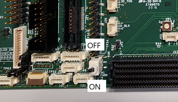
To power up the DLPC4430EVM, a 12 V, 5 A power supply is needed. Make sure the power supply is functional and the switch SW1 on the EVM is set to off before connecting the power supply to the EVM. Connecting the power supply when the switch is in the off position can prevent damage to the DLPC4430EVM from poor power connections. The figure below shows SW1 in the on position.
 Figure 2-2 ON/OFF Switch
Once the power supply has been connected to the DLPC4430EVM, the switch SW1 can be flipped to the “on” position. The user can then plug in the USB cable into the board to prepare for programming the board.