JAJU528B August   2022  – January 2023 OPA388-Q1


  1.   概要
  2.   リソース
  3.   特長
  4.   アプリケーション
  5.   5
  6. 1System Description
    1. 1.1 Key System Specifications
  7. 2System Overview
    1. 2.1 Block Diagrams
    2. 2.2 Highlighted Products
      1. 2.2.1 TPSI2140-Q1
      2. 2.2.2 AMC1301-Q1
      3. 2.2.3 SN6501-Q1
    3. 2.3 System Design Theory
      1. 2.3.1 Isolation Leakage Current Theory
      2. 2.3.2 High-Voltage Measurement
  8. 3Hardware, Testing Requirements, and Test Results
    1. 3.1 Required Hardware
    2.     Hardware with Solid-State Relay
    3. 3.2 Testing and Results
      1. 3.2.1 Test Setup
      2. 3.2.2 Isolation Tests
        1. 3.2.2.1 Normal Conditions
        2. 3.2.2.2 Isolation Error at HV Positive
        3. 3.2.2.3 Isolation Error at HV Negative
        4. 3.2.2.4 Isolation Error at ¼ HV Battery Voltage
        5. 3.2.2.5 Isolation Error at ¾ HV Battery Voltage
        6. 3.2.2.6 Isolation Error at the Middle of an HV Battery Voltage
      3. 3.2.3 Solid-State Relay Isolation Tests
        1. 3.2.3.1 Normal Conditions
        2. 3.2.3.2 Isolation Error at HV Positive
        3. 3.2.3.3 Isolation Error at HV Negative
        4. 3.2.3.4 Isolation Error at ¼ HV Battery Voltage
        5. 3.2.3.5 Isolation Error at ¾ HV Battery Voltage
        6. 3.2.3.6 Isolation Error at the Middle of an HV Battery Voltage
      4. 3.2.4 High Voltage Measurements
      5. 3.2.5 Isolation Measurement Analysis
      6. 3.2.6 Error Analysis
  9. 4Design Files
    1. 4.1 Schematics
    2. 4.2 Bill of Materials
    3. 4.3 PCB Layout Recommendations
      1. 4.3.1 Layout Prints
    4. 4.4 Altium Project
    5. 4.5 Gerber Files
    6. 4.6 Assembly Drawings
  10. 5Software Files
  11. 6Related Documentation
  12. 7Trademarks
  13. 8Revision History

Testing and Results

Solid-State Relay test results are shown below original design testing see Solid-State Relay Isolation Tests.

Measuring system isolation is possible by breaking the isolation internal to this reference design. For this task, build a load card to simulate the isolation error in the system. This card typically consists of various high-voltage resistors and switches to simulate different error conditions (see Figure 3-5).
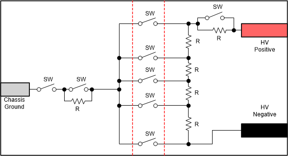
GUID-5E43A108-384E-4433-8D6E-42431A6E2206-low.gifFigure 3-5 TIDA-01513 Isolation Breakage Load Card

When building the isolation breakage load card, be sure to follow high-voltage class safety precautions and laboratory safety requirements. Choose the resistors (R) based on high battery voltage, power dissipation, and the testing targets of the system. Switches (SW) must withstand the open contact voltage and support proper insulation for handling the switches. Build the load card based on the resources available and number of tests planned. Users can also build the load card by using relays with external controls through a signal generator or software.