JAJU858 December 2022
- 概要
- リソース
- 特長
- アプリケーション
- 5
- 1System Description
-
2System Overview
- 2.1 Block Diagram
- 2.2
Design Considerations
- 2.2.1
Isolated AC/DC Power Supply Design
- 2.2.1.1 Input Bulk Capacitance and Minimum Bulk Voltage
- 2.2.1.2 Transformer Turns-Ratio, Primary Inductance, and Primary Peak Current
- 2.2.1.3 Transformer Parameter Calculations: Primary and Secondary RMS Currents
- 2.2.1.4 Main Switching Power MOSFET Selection
- 2.2.1.5 Rectifying Diode Selection
- 2.2.1.6 Output Capacitor Selection
- 2.2.1.7 Capacitance on VDD Pin
- 2.2.1.8 Open-loop Voltage Regulation Versus Pin Resistor Divider, Line Compensation Resistor
- 2.2.1.9 Feedback Elements
- 2.2.1.10 Backup Power Supply
- 2.2.1.11 Supercapacitor Selection
- 2.2.1.12 Supercapacitor Charger Design
- 2.2.2 Control Pilot Signal Interface
- 2.2.3 Relay Drive and Weld Detect
- 2.2.4 Residual Current Detection
- 2.2.1
Isolated AC/DC Power Supply Design
- 2.3 Highlighted Products
- 3Hardware, Testing Requirements, and Test Results
- 4Design and Documentation Support
- 5About the Author
2.2.3 Relay Drive and Weld Detect
The primary functionality of the EVSE is the reliable control of large currents directed toward an electric vehicle at the mains voltage. In a normal use case, the relay or contactor must be held closed for several hours to fully charge a vehicle; however, the relays cannot be welded because of safety concerns. If something fails in the control system, the relays must fail open. These high current relays or contactors can typically draw tens to hundreds of milliamps as an inductive load, requiring specific drive architectures.
Because of the amount of time that a relay or contactor requires to remain powered, an efficient drive device is preferred to the typical Darlington array, or even discrete transistor configuration. For this reason, the DRV8220 current controller is selected to drive the relays or contactors in the design. The DRV8220 device is designed to regulate the current with a well-controlled waveform to reduce power dissipation.
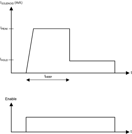
Relays and contactors use electromechanical solenoids for their operation. Activation starts when EN pin voltage is pulled high either by an external driver or internal pullup. Once the EN pin is driven to GND, the DRV8220 device allows the solenoid current to decay to zero. The solenoid current is ramped up fast to enable opening of the relay or contactor. After initial ramping, the solenoid current is kept at a peak value to maintain correct operation, after which the current is reduced to a lower hold level to avoid thermal problems and reduce power dissipation.
 Figure 2-4 Typical Current Waveform Through the Solenoid
For safety reasons, detecting the output voltage of the primary relay is critical. The contacts can experience arcing and become fused together, providing power to the plug even when the contacts are not enabled. Checking that the operation completed correctly is important and must be done every time the relay is opened. To implement this check, the ISO1212 fully-integrated, isolated digital-input receiver is used to sense line voltage.
The outputs (OUT1 and OUT2) from the ISO1212 device are GPIO-level DC signals that are high when voltage is present and are fed directly into the MCU for fault detection. For this reference design, the high and low thresholds are set to 125 VRMS and 121 VRMS, respectively. The full circuit is shown in Figure 2-5. To learn more about AC and DC detection with ISO1212, see ISO121x Threshold Calculator for 9V to 300V DC and AC Voltage Detection.