SLOA198A September 2014 – December 2021 DRV2665 , DRV2667 , DRV2700 , DRV8662
- Trademarks
- 1 Boost Converter Basics
- 2 DRV8662, DRV2700, DRV2665, and DRV2667 Boost Converter
- 3 Configuring the Boost Converter
- 4 Boost Converter Output Voltage
- 5 Calculating the Load Current
- 6 Selecting an Inductor
- 7 Calculate the Maximum Boost Current
- 8 Output Capacitor Selection
- 9 Input Capacitor Selection
- 10PCB Layout
- 11Examples
- 12Revision History
2 DRV8662, DRV2700, DRV2665, and DRV2667 Boost Converter
The DRV8662, DRV2700, DRV2665, and DRV2667 use a hysteretic boost converter design to generate the high voltage needed to drive Piezos. This section describes the basic operating principle of the hysteretic boost converter.
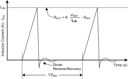
The hysteretic boost converter uses fairly simple feedback to control the timing and frequency of the switch. The ILIM value in the following figure is the peak current through the inductor every time the switch turns on. Once the peak current is reached, the switch opens. The peak inductor current of the DRV8662, DRV2665, and DRV2667 is set by the resistor on the REXT pin (pin 15).

The boost converter only switches when the output voltage (VBST) is below the final target value, meaning that it will only switch when it needs to. Unlike a fixed-frequency boost converter design, the hysteretic boost converter design has a continually varying switching frequency and is load-dependent. Note that the DRV8662, DRV2665, and DRV2667 have forced switching at approximately 37 kHz.