SLYA048B March   2020  – June 2021 FDC1004 , FDC1004-Q1 , FDC2112 , FDC2112-Q1 , FDC2114 , FDC2114-Q1 , FDC2212 , FDC2212-Q1 , FDC2214 , FDC2214-Q1 , LDC0851 , LDC1001 , LDC1041 , LDC1051 , LDC1101 , LDC1312 , LDC1312-Q1 , LDC1314 , LDC1314-Q1 , LDC1612 , LDC1612-Q1 , LDC1614 , LDC1614-Q1 , LDC2112 , LDC2114 , LDC3114 , LDC3114-Q1


  1.   Trademarks
  2. 1Inductive and Capacitive Theory of Operation
    1. 1.1 Inductive Sensing Theory of Operation
    2. 1.2 Capacitive Sensing Theory of Operation
  3. 2FDC: Capacitive Level Sensing
    1. 2.1 Capacitive Technology Benefits in Liquid Level Sensing
    2. 2.2 Getting Started With Capacitive Liquid Level Sensing
    3. 2.3 Device Selection
    4. 2.4 Design Challenges and Additional Collateral
  4. 3LDC: Inductive Touch Buttons
    1. 3.1 Inductive Technology Benefits in Buttons
    2. 3.2 Getting Started With Inductive Buttons
    3. 3.3 Device Selection
    4. 3.4 Design Challenges and Additional Collateral
  5. 4LDC: Incremental Encoder and Event Counting
    1. 4.1 Inductive Technology Benefits in Incremental Encoders
    2. 4.2 Getting Started With an Inductive Incremental Encoder
    3. 4.3 Device Recommendations
    4. 4.4 Design Challenges and Additional Collateral
  6. 5LDC: Metal Proximity Sensor
    1. 5.1 Inductive Technology Benefits in Metal Proximity Detection
    2. 5.2 Criteria to Consider when Choosing Inductive Sensing for Metal Proximity Applications
      1. 5.2.1 Metal Target Movement in Relation to Inductive Coil
      2. 5.2.2 Sensing Distance
      3. 5.2.3 Size and Shape of Metal Target
      4. 5.2.4 Speed (Sample Rate versus Resolution)
      5. 5.2.5 Environmental Compensation
    3. 5.3 Getting Started With Inductive Metal Proximity Sensing
    4. 5.4 Device Recommendations
    5. 5.5 Design Challenges and Additional Collateral
  7. 6Revision History

Device Selection

Figure 3-2 shows the device selection flow chart.
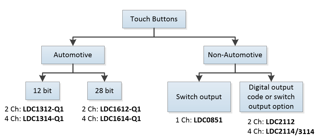
GUID-A658EC1D-BEA7-4A83-881F-E7F314DA1F7B-low.pngFigure 3-2 Inductive Touch Device Selection Flow Chart
Table 3-1 Device Recommendations
DeviceFeatures/Benefits

LDC1612 (Q1)

LDC1614 (Q1)

LDC1312 (Q1)

LDC1314 (Q1)

  • High resolution (LDC161x = 28 bit) allows for accurate detection of different conductive targets
  • Sensing range beyond 2 coil diameters (LDC161x) enables small coil design for smaller form factors
  • Qualified for automotive applications

LDC2112

LDC2114

  • Low power (6 µA at 0.625 SPS) optimized for battery-powered applications
  • Baseline tracking algorithm compensates for temperature and other environmental drifts over time (this feature is always on)

LDC3114-Q1

  • Pin and register compatible to LDC2114

  • Raw data mode to access pre-processed measurement data

  • Baseline tracking algorithm to compensate for drift can be disabled or enabled

  • Qualified for automotive applications

LDC0851

  • Push/pull output for simple applications (lowest cost)