SPRUJ87 june 2023
2.3 Interfaces
Major Components and Location
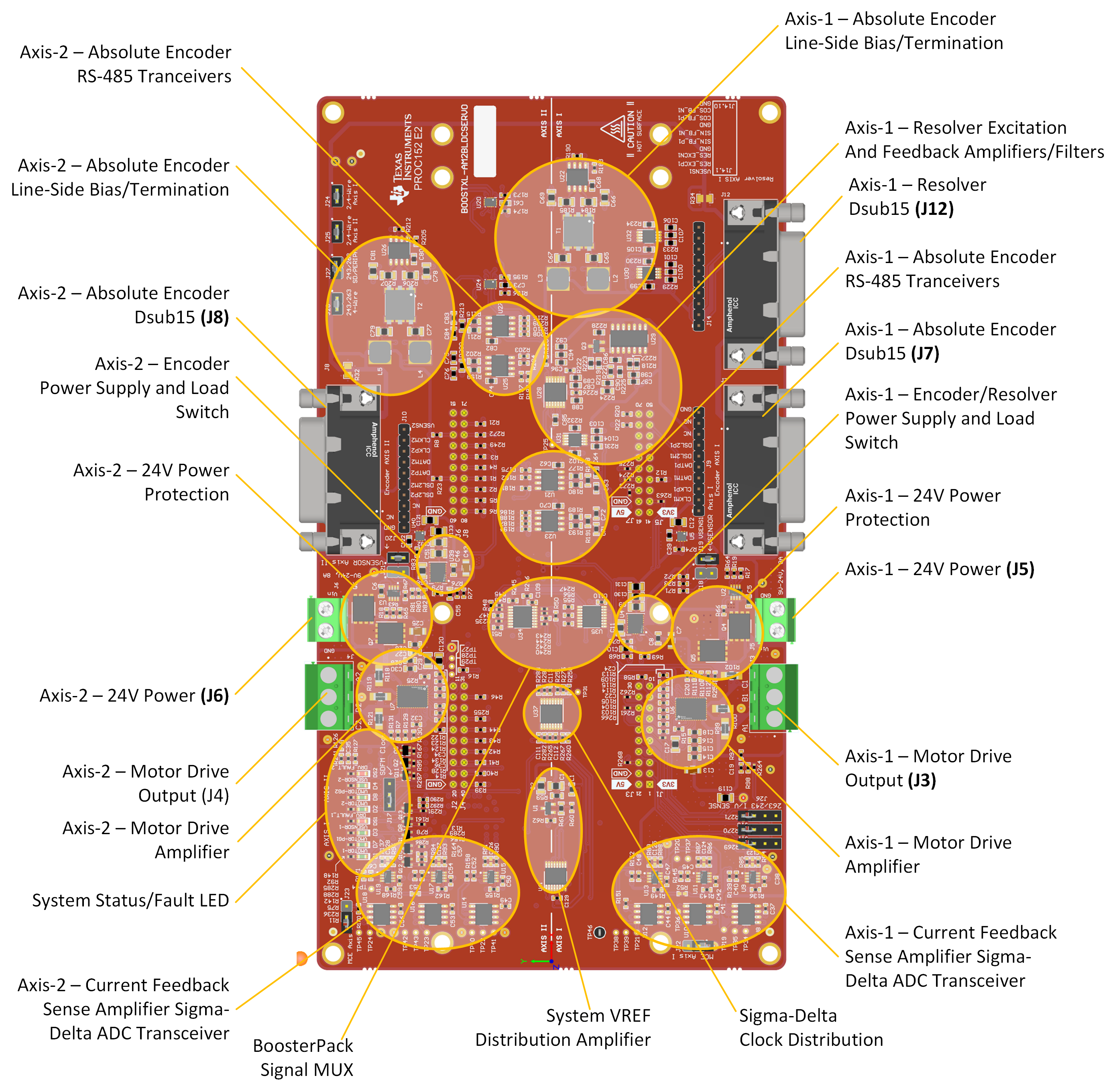
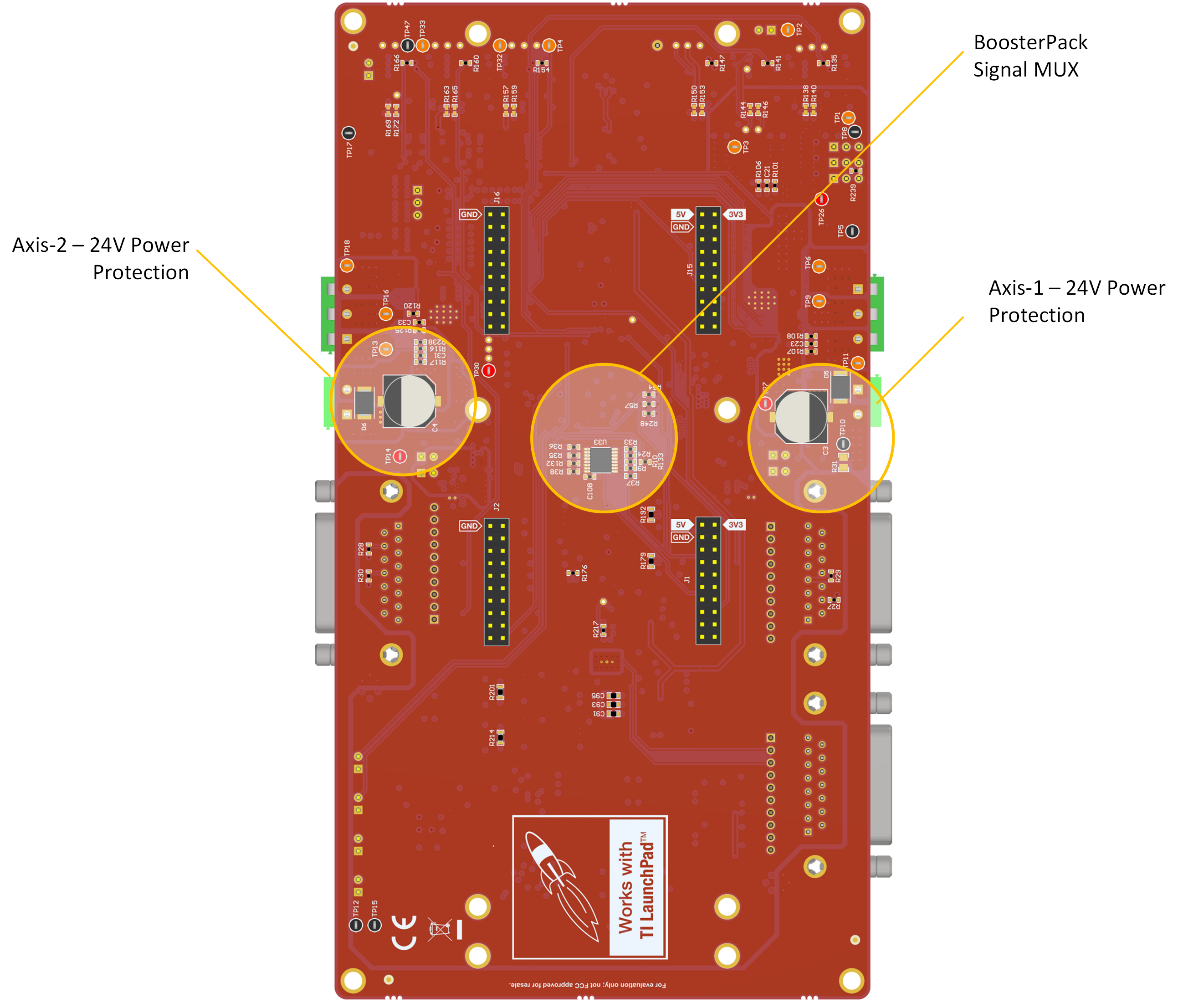
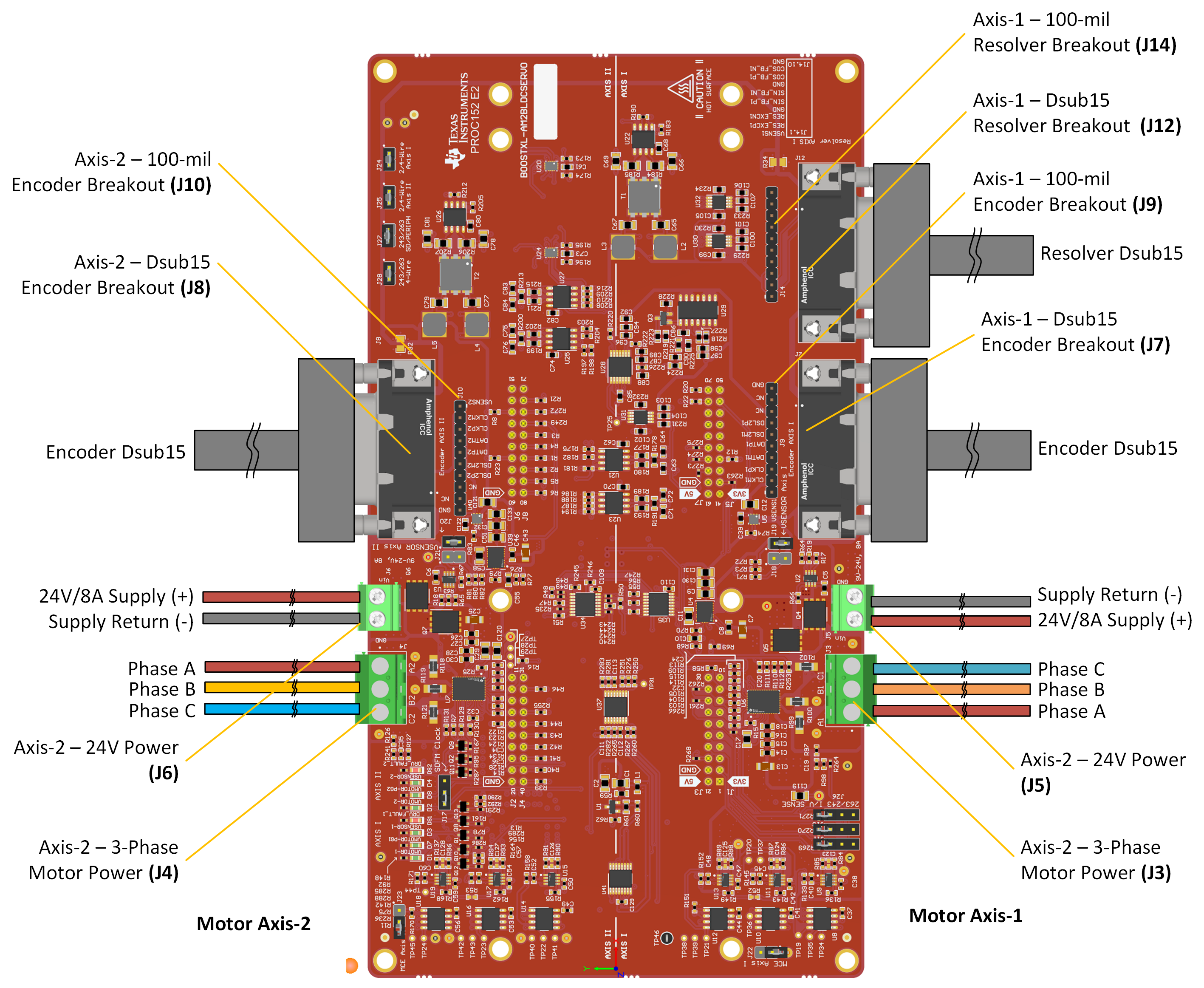
The below figures show the location of major connectors, components and circuit functions used on this design.
BP-AM2BLDCSERVO Top View, Major Component Areas and Connectors Highlighted
 Figure 2-2 BP-AM2BLDCSERVO Top View,
Major Component Areas and Connectors Highlighted
 Figure 2-3 BP-AM2BLDCSERVO Bottom View,
Major Component Areas and Connectors Highlighted
 Figure 2-4 BP-AM2BLDCSERVO Top View -
Connectors and Cables Overview
 Typical Usage
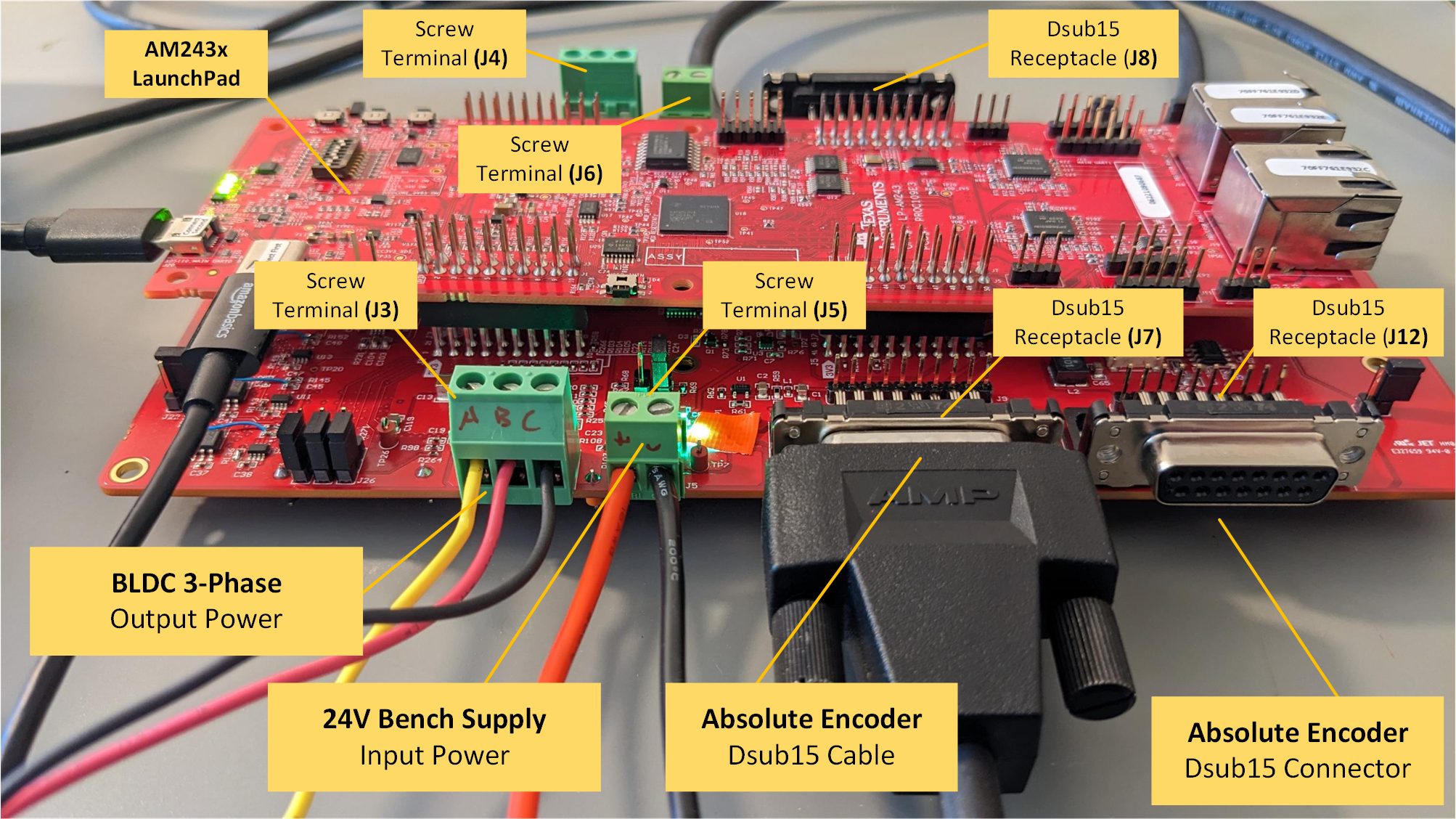
A typical setup for an axis-1, BLDC motor control scenario is shown below. The bench power, motor drive output and absolute encoder cables are shown attached. The attached LP-AM243 is shown with USB-C power and XDS110 debugger cable also attached.
 Figure 2-5 BP-AM2BLDCSERVO and LP-AM243
LaunchPad - Axis-1 Power, Motor and Encoder cables attached