SPRUJ87 june 2023
2.6 Mechanical
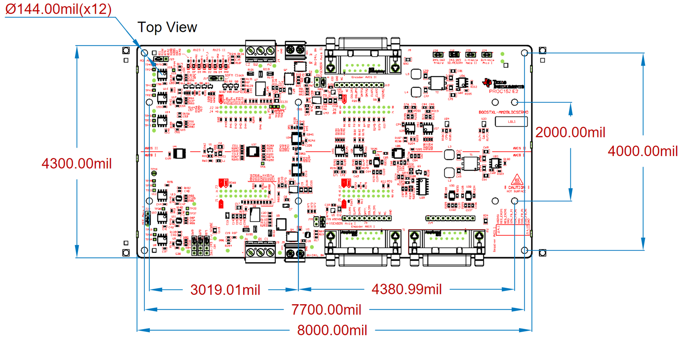
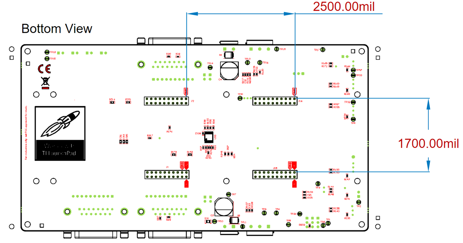
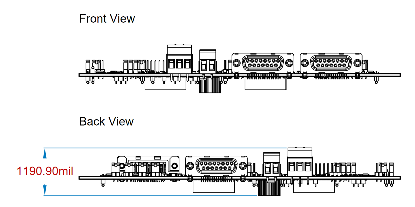
The following tables and figures present the overall mechanical dimensions, BoosterPack connector relative placement and mounting hole dimensions and locations. For further mechanical detail please refer to the board design file package where STEP 3D model files have been provided. This STEP model was exported from the source Altium Designer CAD package.
| Dimension | Value | Unit |
|---|---|---|
| Overall Width | 8000 | Mils |
| Overall Depth | 4300 | Mils |
| Overall Height | 1190.90 | Mils |
| Mount Hole Diameter | 144.0 | Mils |
 Figure 2-12 BP-AM2BLDCSERVO PCB Assembly –
Top View
 Figure 2-13 BP-AM2BLDCSERVO PCB Assembly –
Bottom View
 Figure 2-14 BP-AM2BLDCSERVO PCB Assembly –
Front/Back View
Figure 2-14 BP-AM2BLDCSERVO PCB Assembly –
Front/Back ViewMounting Holes
The board includes 4x 144 mil diameter corner mounting holes. An additional 8x 144 mil diameter holes match the LP-AM243 and the LP-AM263 LaunchPad to allow the LaunchPad boards to be secured through standoffs. For basic usage, the LaunchPad 80-pin connectors provide a strong retention force.