SPRUJ87 june 2023
2.9 Motor Current Feedback
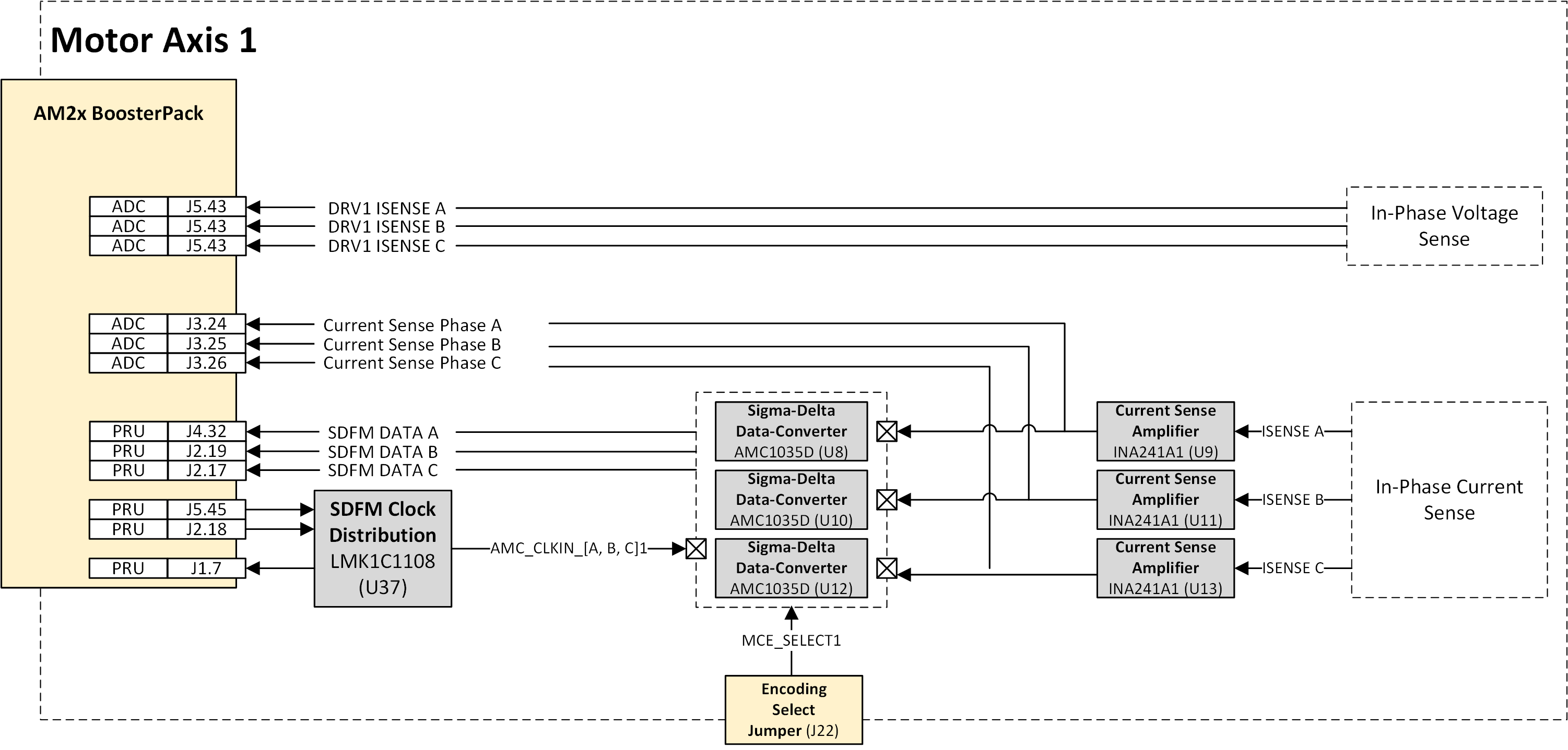
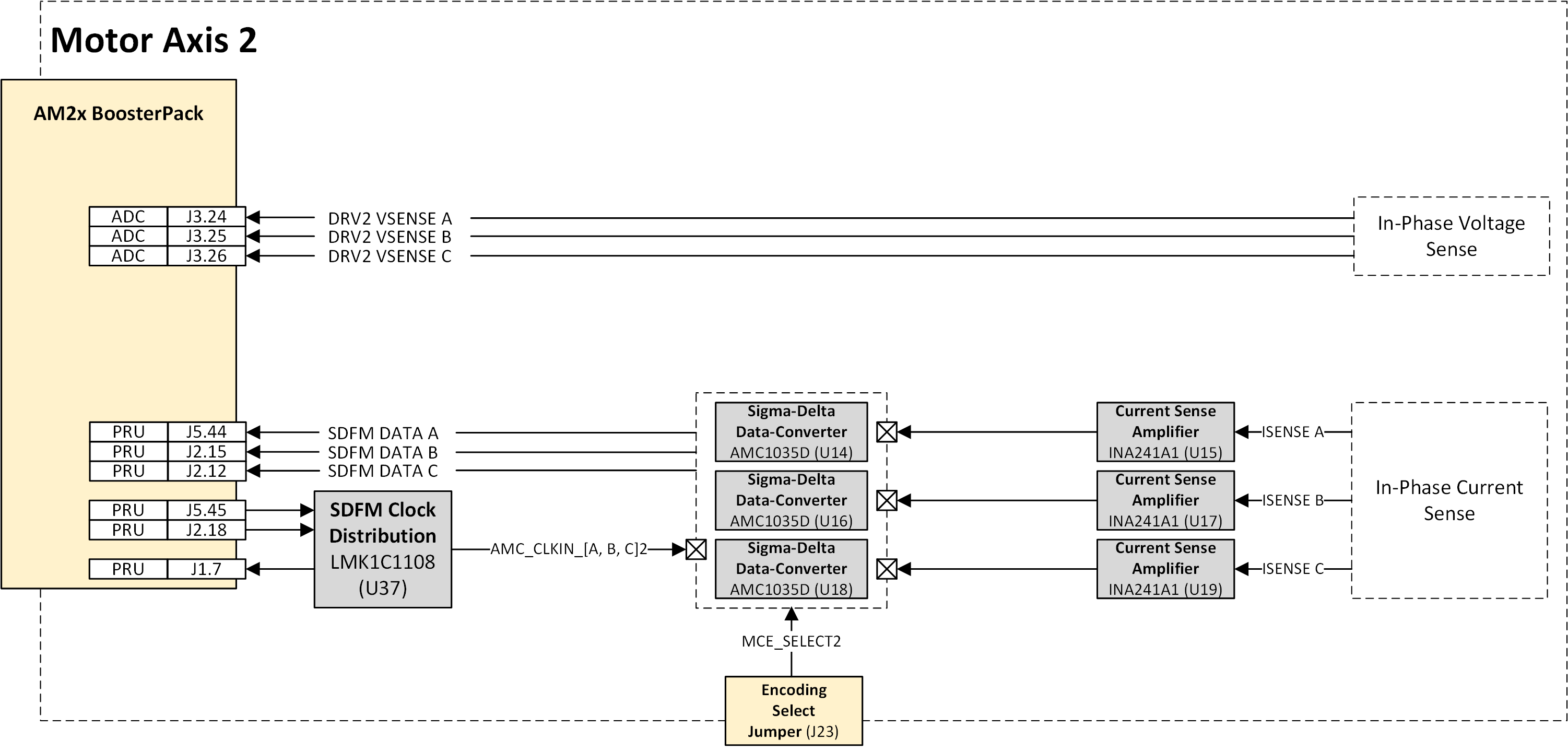
The BP-AM2BLDCSERVO supports multiple current feedback paths for current feedback control. Direct current sense paths route current sense amplifier output directly to the AM263x SAR ADC LaunchPad channels. The other path utilizes a set of onboard AMC1035 Sigma-Delta Modulator ADC and then routes the digital samples to the PRU peripheral inputs of the AM2x device. Each path is designed to support the different current sense capabilities of the attached AM2x MCU.
- The INA241A sense amplifiers provide the voltage proportional to the current through in-line resistors on each motor output phase. This path is routed to AM263x SAR ADC pinout of the Launchpad connectors.
- The DRV8316 provides an internal sense and amplifier path for current through the low-side FET of each half-bridge. See the for a full description of the different feedback paths. This path is routed to the AM263x SAR ADC pinout of the LaunchPad connectors.
- The AMC1035 path provides sampled current feedback in a bitstream modulated format. This is intended to be used with the AM2x PRU SDFM demodulation firmware.
 Figure 2-20 Axis-1 Motor Current Feedback
Paths
 Figure 2-21 Axis-2 Motor Current Feedback
Paths
Figure 2-21 Axis-2 Motor Current Feedback
PathsINA241 ADC Current Feedback
As shown in the above axis-1 motor current feedback figure, INA241A is used to amplify the small shunt voltage. The INA241A provides a fixed 10x gain and common-mode voltage set by the REF1 and REF2 inputs.
This output gain and common-mode setup are intended to provide good usage of the available AMC1035D linear range and be compatible with the AM263x SAR ADC input range.
 Figure 2-22 Motor Current Feedback – Current Sense Path
See the INA241A data sheet for more information on this device.
Programmable Realtime Unit (PRU) Sigma-Delta Modulator (SDFM) Current Feedback
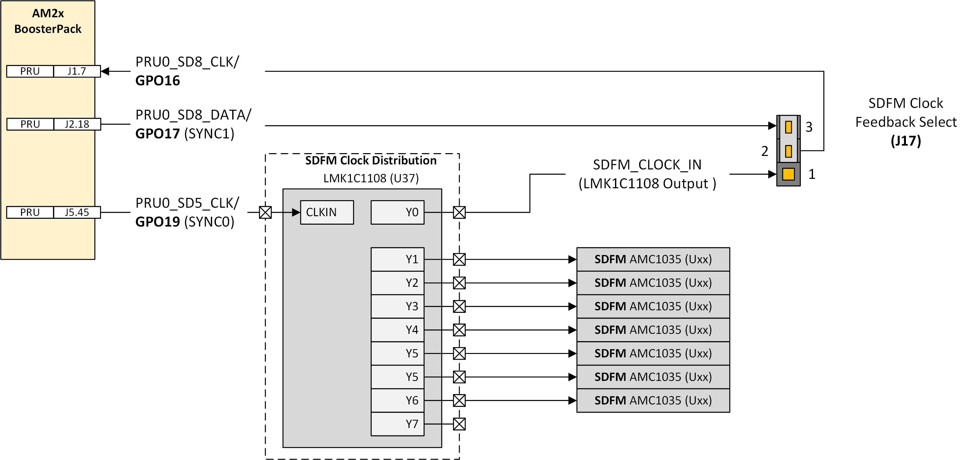
An onboard array of AMC1035 Sigma-Delta modulators provides digital current feedback for the AM2x PRU SDFM peripheral. The data path from each AMC1035 is directly routed to a PRU SD Data pin on the LaunchPad pinout. The AMC1035 clocking is provided through an onboard, LMK1C1108, low-jitter clock distributor. The input to this clock distribution comes from the PRU SYNC0 source output.
A jumper selector (J17) is used to select which clock distribution tap point is used to provide the PRU SD peripheral input clock. Either the SYNC1 (alternate clock output) can be selected or one of the SDFM clock distribution channels can be selected. The PRU peripheral provides for internal clock routing to each of the individual PRU SD Data channels.
 Figure 2-23 PRU SDFM Motor Current Feedback – Data/Clock Paths
The AMC1035 data clock is generated by the PRU SYNC0 output present on PRU_SD5_CLK. This is fanned out to each of the individual AMC1035 devices through an LMK1C1108 1:8 clock distribution IC (U37). For clocking data back into the PRU from the AMC1035, either one of the LMK1C1108 output channels can be used or a separate PRU generated SYNC1 signal (present on present on PRU_SD5_DATA) can be selected. Clock feedback is selected through the (J17) jumper.
 Figure 2-24 PRU SDFM Motor Current Feedback – Clock Tree Detail
See the AMC1035D and INA241Ax data sheets for a full description of these two components operations.