SPRUJ87 june 2023
2.1 Assembly Instructions
The following assembly steps must be followed when starting with a new BP-AM2BLDCSERVO BoosterPack and a new LP-AM2x LaunchPad.
- BP-AM2BLDCSERVO and LP-AM2x LaunchPad are both powered down.
- BP-AM2BLDCSERVO and LP-AM2x LaunchPad can be attached through their LaunchPad connectors.
- Attach LP-AM2x LaunchPad power and debugging cable (if necessary) and keep LaunchPad unpowered.
- Attach 24 V DC supply (current limit to 8A) to the BoosterPack screw terminals and keep supply powered off.
- Attach motor drive output to the BoosterPack screw terminals.
- Attach encoder power/data cable/wires to the BoosterPack Dsub15 connectors or 100-mil pitch headers.
- Attach resolver power/data cable/wires to the BoosterPack Dsub15 connectors or 100-mil pitch headers.
- Verify that all motor and encoder shafts are free and clear of obstructions prior to powering on and testing system.
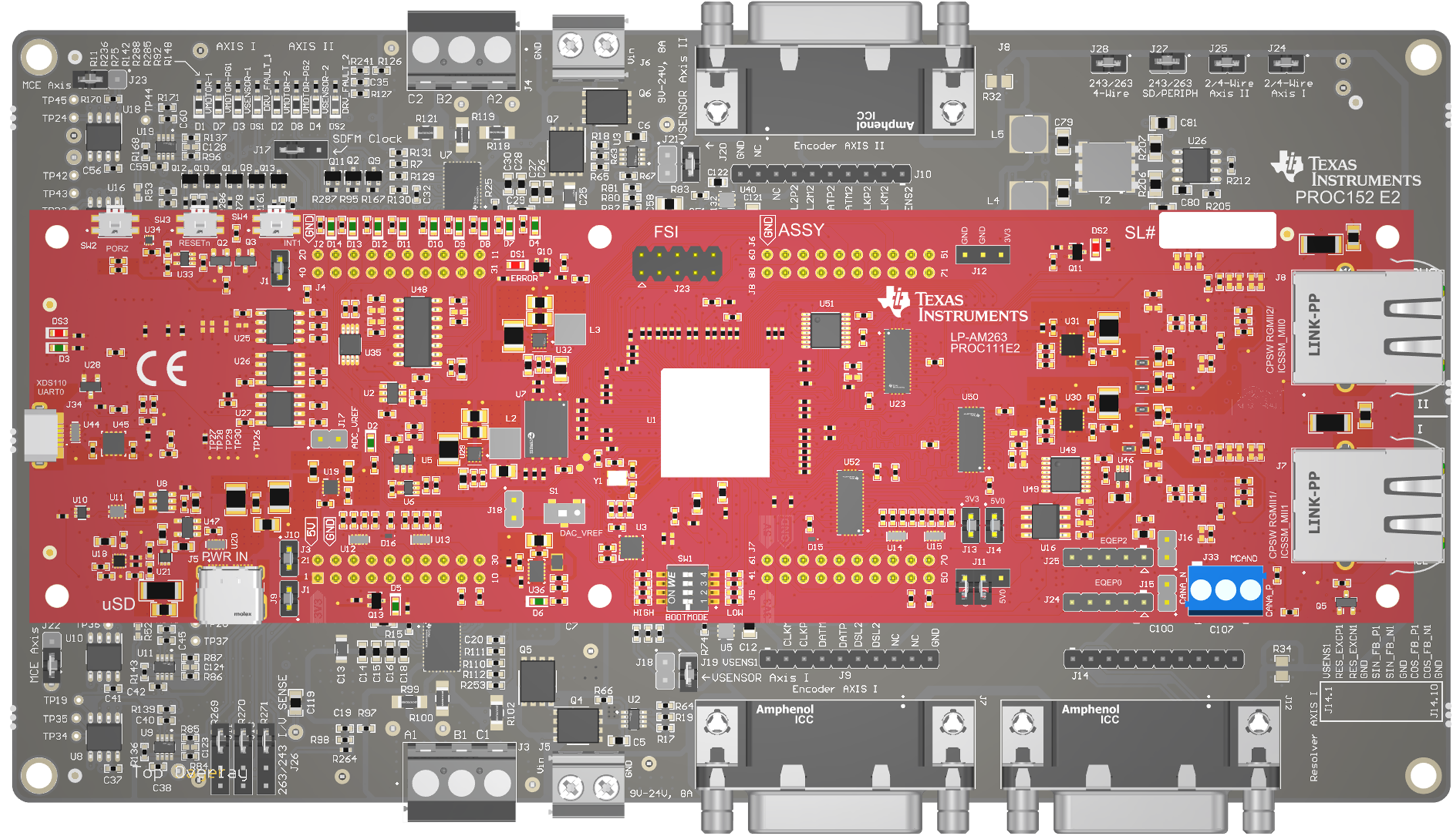
 Figure 2-1 LP-AM243 mated to
BP-AM2BLDCSERVO