SSZTC32 october 2015 UCC28911
In applications like smart meters and motor drives, the power supplies must convert high-input voltages into low DC voltages for microcontrollers or IGBT drivers. For example, 440VAC or 480VAC are common three-phase AC voltages across the world that smart meters generally need to access. In motor drive applications, you might encounter even higher voltages.
Converting high-input voltages into low DC voltages like 12V, 5V or 3.3V with a low Bill of Material (BOM) cost is an interesting topic, since most commercial components used for high-voltage step-down converters are designed for universal AC input (85VAC to 264VAC). In this post, I’ll explain how to make wise topology/component selections for high-voltage step-down conversion.
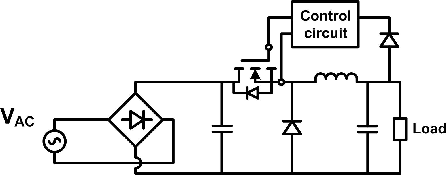
In applications that do not require isolation between the high-voltage input and the DC output (like smart meters), a buck converter is still the top choice because of its simplicity. For example, the 85-318VIN, 15VOUT, 1AOUT, AC/DC Buck Converter TI Designs reference design uses a high-side DCM buck converter (simplified schematic shown in Figure 1) for a voltage conversion from 459VAC to 15VDC. You will need to address two factors in high-voltage step-down buck-converter designs like this one:
- The freewheeling diode reverse-recovery effect.
- The controller’s minimum on-time limitation.
 Figure 1 The Non-isolated AC/DC
Converter
Figure 1 The Non-isolated AC/DC
ConverterRemember that the switching losses induced by freewheeling diode reverse recovery increase as the input voltage increases. Switching losses may dominate the power dissipation of the MOSFET, especially when the converter operates in continuous conduction mode (CCM). Thus, if you want CCM operation for high-voltage AC/DC non-isolated conversion, you might need a Silicon Carbide (SiC) diode to reduce switching losses due to the reverse recovery effect.. For example, the AC/DC Buck Converter with 85VAC-318VAC Input and 15V at 0.8A Output TI Designs reference design uses a SiC diode with a CCM buck converter for a compact auxiliary power supply.
Moreover, buck-converter duty cycles become extremely small in high-voltage AC/DC conversion. For a 440VAC to 15VDC conversion, the duty cycle could be smaller than 2% in a DCM buck converter. When operating the converter at a high switching frequency, it is possible to hit the controller minimum on-time limitation; for example, the UCC28911 requires a 420nS minimum on time. In other words, if you use the UCC28911 in a 440VAC to 15VDC conversion as a buck-converter controller, the converter must operate at a switching frequency lower than 45kHz.
For high-voltage step-down applications that require isolation, a flyback converter might provide the lowest BOM cost when compared to other topologies. In addition, you can use a flyback converter in applications with a wide-input voltage range. Its low cost and suitability for wide-input voltages make flyback converters the top choice in isolated high-voltage step-down conversions. However, a flyback converter requires its input switch to have a voltage rating higher than the maximum input voltage, which could greatly increase BOM cost. For example, a flyback converter with a 800VDC input might need an input switch with a 1200V rating (see the 300VDC-800VDC Input, 54W Four-Channel-Output PSR Flyback with SiC-FET TI Designs reference design). MOSFETs with a 1200V voltage rating are generally expensive, even if you exclude the also-expensive SiC MOSFETs.
If the output power level is low, you can use a low-cost high-voltage bipolar junction transistor (BJT) as a flyback input switch like in the Ultrawide Input Range, Dual-Output, Offline AC/DC Bias Supply with PSR Control and BJT Switch TI Designs reference design. One important thing about the high-voltage BJT flyback design is that high-voltage BJTs generally have low DC gains. Thus, you must make sure that the peak input current in your design is achievable with limited BJT DC gains.
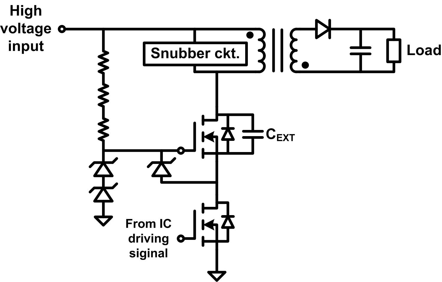
If the output power level is high (>30W), consider using an SiC MOSFET like I did in the 300VDC-800VDC Input, 54W Four-Channel-Output PSR Flyback with SiC-FET TI Designs reference design for higher converter efficiency, or use cascode MOSFETs configuration (shown in Figure 2) like that in the 400V to 690VAC Input, 50W Flyback Isolated Power-Supply Reference Design for Motor Drives for low BOM cost.
 Figure 2 Flyback Converter with Cascode
MOSFETs Configuration
Figure 2 Flyback Converter with Cascode
MOSFETs ConfigurationIn my next post, I’ll address detailed operations and key considerations of converters with cascode MOSFETs.
Additional Resources
- Check out these other TI Designs reference designs: