DLPU106A March 2021 – October 2021 DLP3021-Q1
2.2 What is in the DLP3021-Q1 Light Engine EVM
The DLP3021-Q1 Light Engine EVM consists of three subsystems and two boards:
DLP3021LEQ1EVM board:
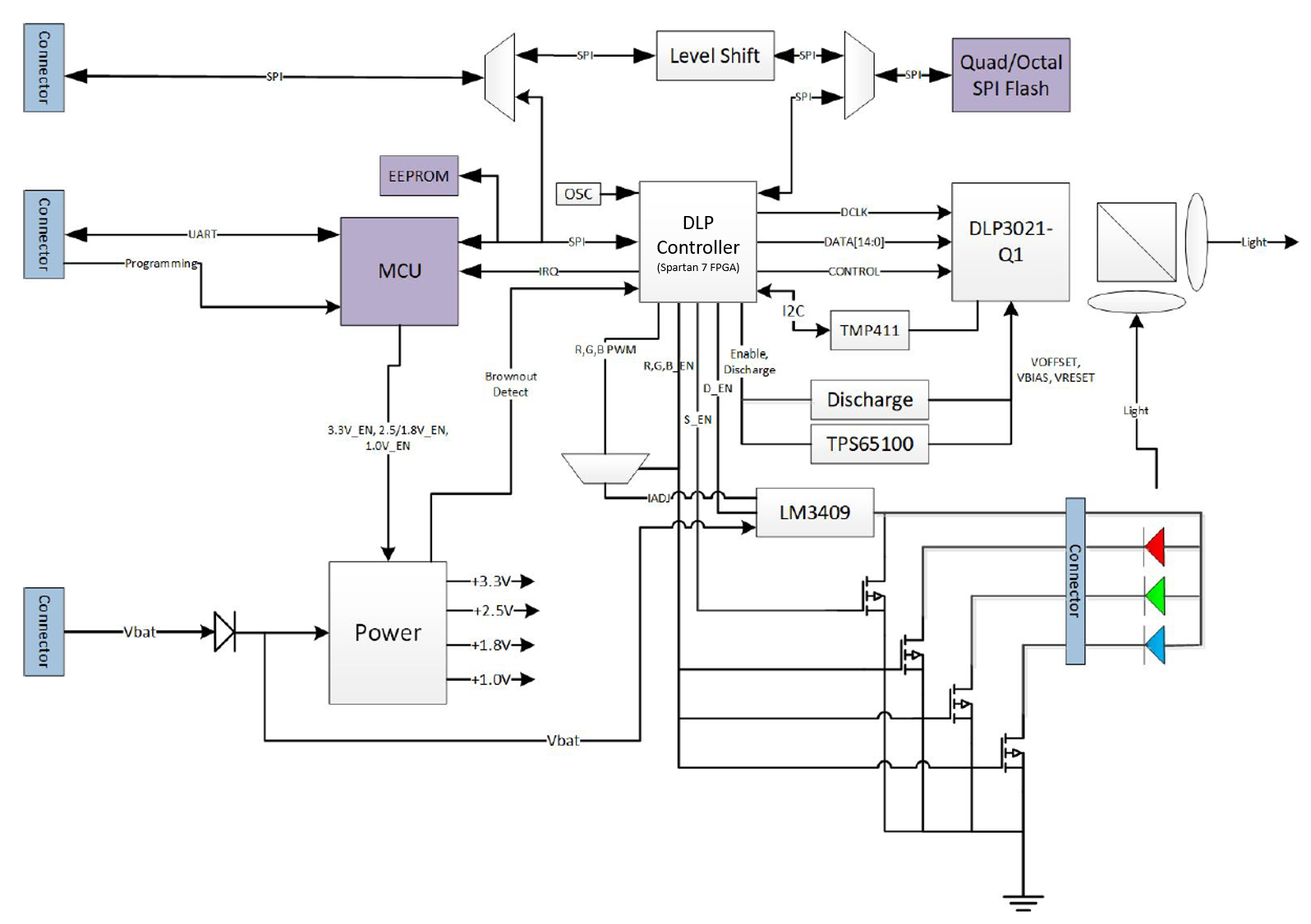
Formatter — Includes the DLP3021-Q1 DMD, FPGA based DMD controller, the MSP430G2553 MCU, external flash memory, and the TPS65100-Q1 PMIC.
Illumination Driver — Includes illumination drivers and FETs.
Light Engine — Compact light engine designed to display images from the formatter.
FTDI C232HM-DDHSL-0 USB to MPSSE serial cable for 3.3V logical level SPI communication with the FPGA based DMD controller and external flash memory. The Cheetah™ USB-to-SPI interface can be used as a faster alternative for USB-to-SPI communication, but must be purchased separately.
-
SPI Adapter board — intermediate board between the FTDI USB-to-SPI cable and DLP3021LEQ1EVM electronics board required for Host Mute and Flash Programming operating modes. Includes toggle switches to change the operating mode of the EVM.
Figure 2-1 shows the block diagram of the DLP3021LEQ1EVM.
 Figure 2-1 DLP3021LEQ1EVM Block Diagram
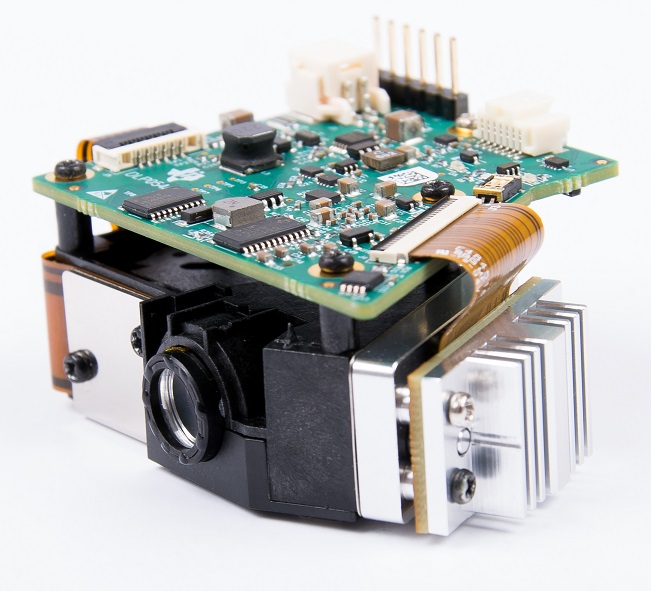
Figure 2-2 shows the assembled DLP3021LEQ1EVM Unit.
 Figure 2-2 DLP3021LEQ1EVM Unit
|
|
||||||||

