DLPU106A March   2021  – October 2021 DLP3021-Q1


  1.   Abstract
  2. 1Trademarks
  3. 2DLP3021-Q1 Electronics EVM Overview
    1. 2.1 Introduction
    2. 2.2 What is in the DLP3021-Q1 Light Engine EVM
      1. 2.2.1 Formatter Subsystem
      2. 2.2.2 Illumination Subsystem
      3. 2.2.3 Light Engine
      4. 2.2.4 Cables
    3. 2.3 Non-Optical Specifications
      1. 2.3.1 Electrical Specifications
      2. 2.3.2 Component Temperature Ratings
      3. 2.3.3 LED Driver Design
      4. 2.3.4 Video Specification
  4. 3Quick Start
    1. 3.1 Kit Assembly Instructions
    2. 3.2 Software Installation
    3. 3.3 Power-Up
    4. 3.4 Select Display Content
    5. 3.5 LED Driver
  5. 4Optics and Mechanics
  6. 5Software
    1. 5.1 DLP Composer
      1. 5.1.1 Default Register Configuration
      2. 5.1.2 Illumination
      3. 5.1.3 Sequence Set
      4. 5.1.4 Degamma Curves
      5. 5.1.5 Image/Video
      6. 5.1.6 Flash Blocks
      7. 5.1.7 Flash Programming
    2. 5.2 DLP Control Program
      1. 5.2.1 Connection
      2. 5.2.2 Scripting
      3. 5.2.3 Registers
      4. 5.2.4 Commands
    3. 5.3 MSP430 Example Code
  7. 6Revision History

Kit Assembly Instructions

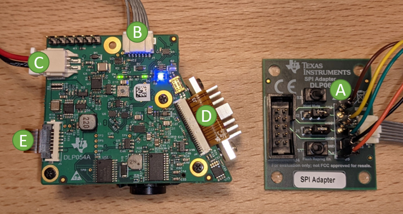
The DLP3021-Q1 Light Engine EVM electronics board is shipped as a fully assembled unit. A diagram of all cable connections is shown in Figure 3-1. The complete light engine assembly is shown in Figure 3-2.
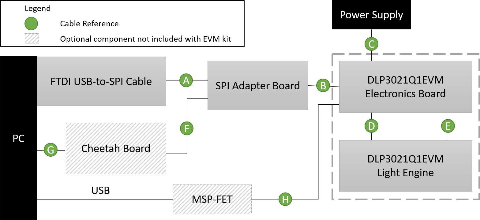
GUID-20210126-CA0I-RH0F-JHRV-MSH8XVMZJT87-low.pngFigure 3-1 Cable Connections
Table 3-1 FTDI C232HM MPSSE Cable to SPI Adapter Board Connections

FTDI Wire Signal (Pin)

FTDI Wire Color

SPI Adapter Board FTDI Header Pin

TCK (2)

Orange

J5-1

GND (10)

Black

J5-2

TDO (4)

Green

J5-3

TDI (3)

Yellow

J5-5

TMS (5)

Brown

J5-7

GUID-20210210-CA0I-RS7L-2PB8-V1JJ91QC2VRR-low.pngFigure 3-2 Assembled DLP3021-Q1 Light Engine EVM with FTDI