DLPU106A March 2021 – October 2021 DLP3021-Q1
5.1.7 Flash Programming
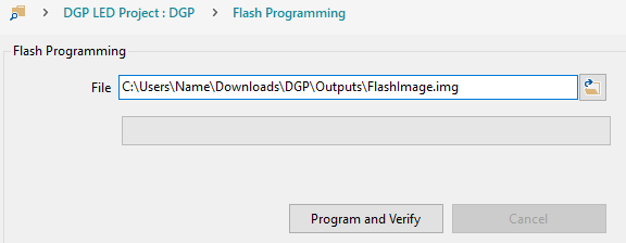
Once the DLP Composer project is configured as desired, use the Flash Programming page to program and verify the flash binary onto the SPI flash memory of the EVM.
 Figure 5-7 DLP Composer - Flash Programming
Follow these steps to flash program the EVM:
Start with the EVM powered-off.
Set the SPI Adapter board to the Flash Programming operating mode.
Connect the FTDI cable interface to the SPI Adapter Board and PC.
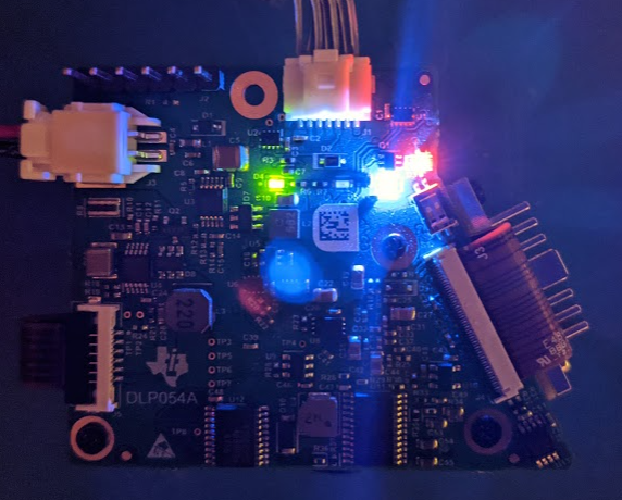
Power-on the EVM. Figure 5-8 shows the LED status of the EVM when in the Flash Programming operation mode.
 Figure 5-8 Flash Programming Operating Mode LED Status
Import and open the DLP3021LEQ1EVM DGP project in DLP Composer.
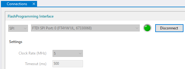
Navigate to the Connections tab. Set to SPI and FTDI SPI Port, then click the Connect button. The virtual green LED should illuminate to indicate a successful connection as shown in Figure 5-9.
 Figure 5-9 DLP Composer - Connections
Build the DLP Composer project using the Project → Build from the menu bar. Ensure the build is completed and successful before proceeding. Note, the build time will vary and can take up to several minutes depending on the size of the image/video content block.
Navigate to the Flash Programming page, and browse to select the flash image file from the following directory: “(dgp_project_root)\Outputs\FlashImage.img”.
Click the Program and Verify button to flash program the EVM. Note, the flash programming time will vary and can take up to several minutes depending on the size of the image/video content block.