SBOA511A March 2021 – September 2021 INA209 , INA219 , INA220 , INA220-Q1 , INA226 , INA226-Q1 , INA228 , INA228-Q1 , INA229 , INA229-Q1 , INA230 , INA231 , INA232 , INA233 , INA234 , INA236 , INA237 , INA237-Q1 , INA238 , INA238-Q1 , INA239 , INA239-Q1 , INA260 , INA3221 , INA3221-Q1
- Trademarks
- 1 Introduction
- 2 Defining Constraints
- 3 Find The Maximum Shunt Value
- 4 Find The Minimum Shunt Value
- 5 Maximum Resolution or Minimum Shunt Loss
- 6 What to Do if the Measurement Range Is Insufficient
- 7 Determine the Current LSB and Calibration Coefficient
- 8 Programming Your Device Registers
- 9 Summary
- 10Revision History
6 What to Do if the Measurement Range Is Insufficient
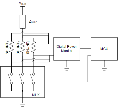
In the event that not a single shunt can satisfy your design constraints, you may need to explore different options. The simplest option might be to use a different device. Devices with lower input offset voltage, with lower input bias current, and with more ADC bits of resolution, typically will allow you to measure a broader range of current. If these are still inadequate, you will need to get creative. One option would be to multiplex a parallel network of shunt resistors like in this Figure 6-1.
 Figure 6-1 Low-side Multiple Shunt Example