SNLU226B February 2018 – April 2021 DS90UB960-Q1
- 1 Introduction
- 2 Features
- 3 Application Diagram
- 4 Major Components
- 5 Quick Start Guide
- 6 Board Connections
- 7 Enable and Reset
- 8 ALP Software Setup
- 9 Troubleshooting ALP Software
- 10Typical Connection and Test Equipment
- 11Termination Device
- 12Typical Test Setup
- 13Equipment References
- 14Cable References
- 15Bill of Materials
- 16PCB Schematics
- 17Board Layout
- 18Revision History
6.2 Power Over Coax Interface
The DS90UB960-Q1EVM offers four Power-over-Coax interfaces (PoC) to connect cameras through a coaxial cable with FAKRA connectors. Power is delivered on the same conductor that is used to transmit video and control channel between the host and the camera. By default, 9V power supply is applied over the coax cable from a 1A LDO (Max 250 mA per PoC interface). Refer to Table 6-3 for other PoC configurations.
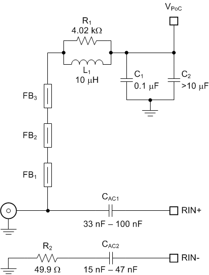
Each PoC interface uses a filter network as shown in Figure 6-1. The PoC network frequency response corresponds to the bandwidth compatible with DS90UB935-Q1 and DS90UB953-Q1 serializers.
 Figure 6-1 Power-over-Coax Network
Compatible with DS90UB935-Q1 and DS90UB953-Q1
Figure 6-1 Power-over-Coax Network
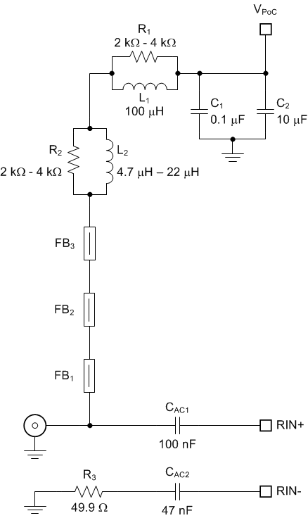
Compatible with DS90UB935-Q1 and DS90UB953-Q1Verify that the power voltage is properly set before plugging into CN1. Power supply is not fused. Over-voltage will cause damage to boards directly connected due to incorrect input power supplies.
 Figure 6-2 Power-over-Coax Network Compatible with DS90UB913A-Q1, DS90UB933-Q1, DS90UB935-Q1, and DS90UB953-Q1
| RX Port | Description of the Required Change |
|---|---|
| RX Port0 | Install L11 (100 µH). |
| Update R90 to 4.02 kΩ | |
| Update C70 to 100 nF, C72 to 47 nF | |
| RX Port1 | Install L13 (100 µH). |
| Update R92 to 4.02 kΩ | |
| Update C71 to 100 nF, C73 to 47 nF | |
| RX Port2 | Install L23 (100 µH). |
| Update R96 to 4.02 kΩ | |
| Update C82 to 100 nF, C84 to 47 nF | |
| RX Port3 | Install L25 (100 µH). |
| Update R98 to 4.02 kΩ | |
| Update C83 to 100 nF, C85 to 47 nF |
| Reference | Signal | Description |
|---|---|---|
| J19 | VFEED_POC1 | Power Over Coax Power Feed Selection 1 |
| Short pins 1-2: +9V power supply from VFEED_LDO1 (Default) | ||
| Short pins 2-3: +5V power supply from 5V_SW | ||
| J22 | VFEED_POC2 | Power Over Coax Power Feed Selection 2 |
| Short pins 1-2: +9V power supply from VFEED_LDO2 (Default) | ||
| Short pins 2-3: +5V power supply from 5V_SW | ||
| J15 | VDD_EXT | Power Over Coax Power Feed using +12V
Main Power (J21) Note: J16 and J14 must be left OPEN if using this configuration |
| Short pins 1-2: +12V power supply to VFEED_POC1 | ||
| Short pins 2-3: +12V power supply to VFEED_POC2 | ||
| J11.1 | VFEED1 | Remote power supply connection to CN1 |
| Short J11.1-2: VFEED_POC1 (Default) | ||
| Short J11.1 & J12.1: VFEED_POC2 | ||
| J11.3 | VFEED2 | Remote power supply connection to CN2 |
| Short J11.3-4: VFEED_POC1 (Default) | ||
| Short J11.3 & J12.2: VFEED_POC2 | ||
| J11.5 | VFEED3 | Remote power supply connection to CN3 |
| Short J11.5-6: VFEED_POC1 (Default) | ||
| Short J11.5 & J12.3: VFEED_POC2 | ||
| J11.7 | VFEED4 | Remote power supply connection to CN4 |
| Short J11.7-8: VFEED_POC1 (Default) | ||
| Short J11.7 & J12.4: VFEED_POC2 |