SPRABJ8B September 2022 – November 2023 AM2631 , AM2631-Q1 , AM2632 , AM2632-Q1 , AM2634 , AM2634-Q1 , AM263P4 , AM263P4-Q1
4 Resets
The AM263x and AM263Px MCUs have two hardware reset sources:
- PORZ: Power on reset (logic low
enable) signal, pin R2
- Should be driven from the power-good circuits of the associated VDD 1.2 V core and VDDS33 3.3 V I/O regulators
- For a valid reset the PORZ signal must transition from logic low to logic high only after the VDD 1.2V core and VDDS33 3.3V I/O regulators are stable, and at their nominal values. For power-on-reset timing requirements, see the device-specific data sheet.
- WARMRSTN: Warm reset (logic low enable) input and reset status output signal,
pin C3
- The power-on the default configuration sets this pin as open-drain output, which outputs the reset status of the device.
- When the device enters reset, this signal is driven logic low.
- When the device is fully out of reset, this signal is driven logic high.
The PORZ is intended to be kept at logic low at initial startup of the system. Once each regulator sourcing the AM263x or AM263Px power pins has been verified to be operating at nominal output voltage, then the PORZ signal can be brought up to logic high. This action will start the MCU boot ROM execution, beginning with sampling of the SOP pins. The AM263x Launchpad implementation utilizes a single SN74LVC1G11 AND gate which takes in as input the open-drain output power-good signals from the onboard DC-DC regulators and an optional push-button reset switch. A weak pull-down resistor is recommended on the PORZ signal to keep the signal at logic low before startup of the system. PORz should be forced low if either VDD 1.2 V or VDDS33 3.3 V rail power goes below the nominal operating range.
For a full description of the power-on and power-off reset sequencing requirements, see the AM263x Sitara™ Microcontroller Data Sheet or AM263Px Sitara™ Microcontroller Data Sheet.
 Figure 4-1 Excerpt From AM263x Launchpad
Schematic – PORZ Generation
Figure 4-1 Excerpt From AM263x Launchpad
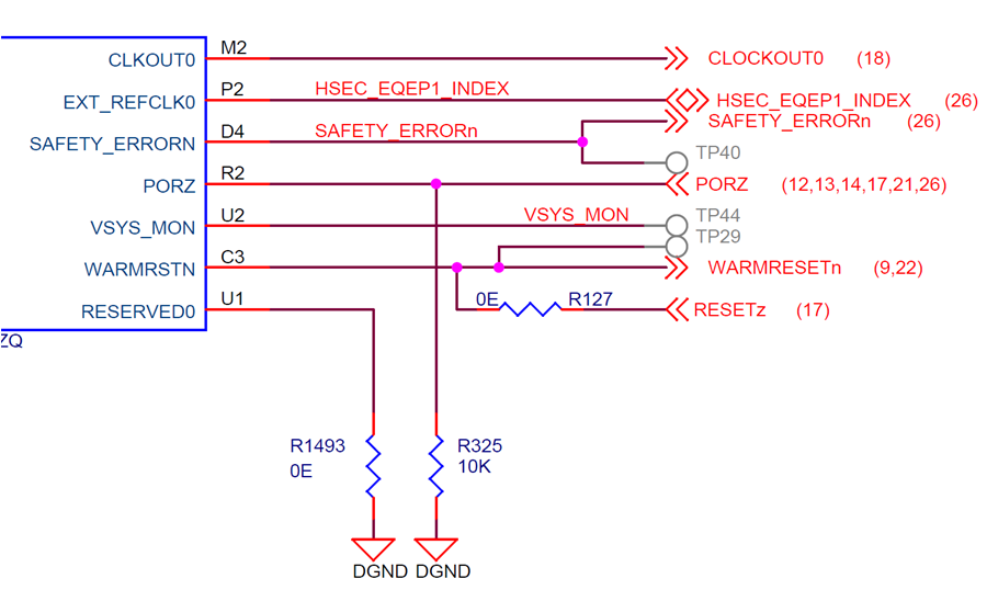
Schematic – PORZ GenerationThe WARMRSTN pin is a multi-purpose software reset input and hardware reset status pin. In the power-on-default configuration, this pin is configured as an open-drain output and requires an external pull-up resistor to VDDS33 3.3 V I/O voltage rail. In this mode, WARMRSTN can be used as an MCU reset indicator and can be used to drive reset input for attached peripheral IC such as Ethernet PHY and memories.
 Figure 4-2 Excerpt From AM263x Control
Card Schematic – PORZ and WARMRSTN Pinout
Figure 4-2 Excerpt From AM263x Control
Card Schematic – PORZ and WARMRSTN PinoutWARMRSTN can also be configured by software as software reset. Additional software reset sources are also available on the AM263x and AM263Px devices. For more information on reset functionality, see the Reset chapter in the AM263x Sitara™ Microcontroller Technical Reference Manual or AM263Px Sitara™ Microcontroller Technical Reference Manual.
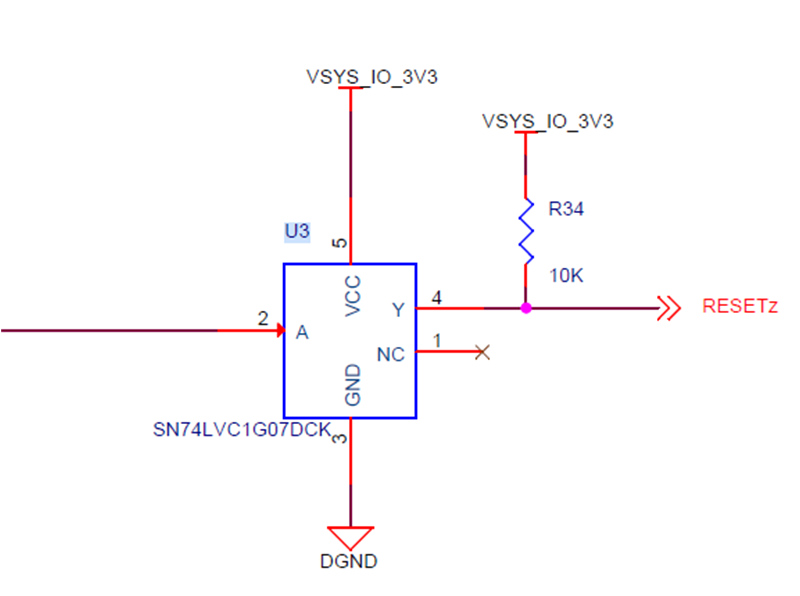
Because of the default open-drain configuration of this pin, if both the reset status output mode and the software reset input mode is needed in a design, it is recommended that open-drain buffers be used to drive the optional reset input status. In the case of the AM263x Control Card, a SN74LVC1G07 open-drain buffer is used to optionally drive the push-button WARMRSTN without conflicting with the reset status output which is used to reset the Ethernet PHY onboard during initial board power-on.
 Figure 4-3 Excerpt From AM263x Control
Card Schematic – WARMRESETN Push-Button Open-Drain Driver