SBAS562B April 2012 – December 2019 AMC1100
PRODUCTION DATA.
- 1 Features
- 2 Applications
- 3 Description
- 4 Revision History
- 5 Pin Configuration and Functions
-
6 Specifications
- 6.1 Absolute Maximum Ratings
- 6.2 ESD Ratings
- 6.3 Recommended Operating Conditions
- 6.4 Thermal Information
- 6.5 Power Ratings
- 6.6 Insulation Specifications
- 6.7 Safety-Related Certifications
- 6.8 Safety Limiting Values
- 6.9 Electrical Characteristics
- 6.10 Insulation Characteristics Curves
- 6.11 Typical Characteristics
- 7 Detailed Description
- 8 Application and Implementation
- 9 Power Supply Recommendations
- 10Layout
- 11Device and Documentation Support
- 12Mechanical, Packaging, and Orderable Information
Package Options
Mechanical Data (Package|Pins)
Thermal pad, mechanical data (Package|Pins)
- DUB|8
Orderable Information
8.2.1.1 Design Requirements
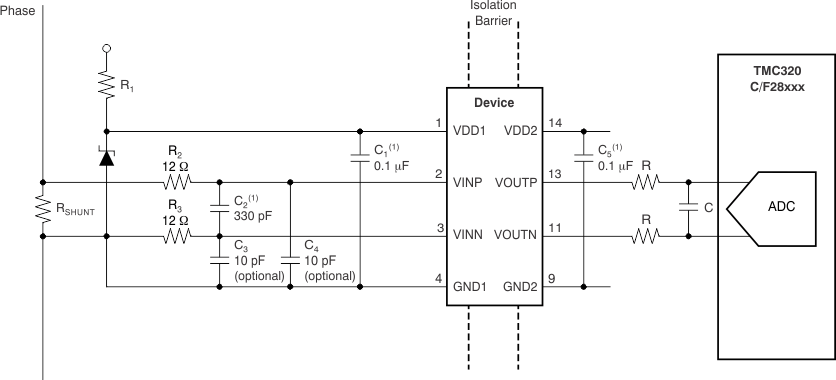
Current measurement through the phase of a motor power line is done via the shunt resistor RSHUNT (in a two-terminal shunt); see Figure 36. For better performance, the differential signal is filtered using RC filters (components R2, R3, and C2). Optionally, C3 and C4 can be used to reduce charge dumping from the inputs. In this case, care must be taken when choosing the quality of these capacitors; mismatch in values of these capacitors leads to a common-mode error at the modulator input. Using NP0 capacitors is recommended, if necessary.
 Figure 36. Shunt-Based Current Sensing with the AMC1100
 The isolated voltage measurement can be performed as described in the Device Functional Modes section.