SLVSCU7A February   2016  – March 2016 DRV10970

PRODUCTION DATA.  

  1. Features
  2. Applications
  3. Description
  4. Revision History
  5. Description (continued)
  6. Pin Configuration and Functions
  7. Specifications
    1. 7.1 Absolute Maximum Ratings
    2. 7.2 ESD Ratings
    3. 7.3 Recommended Operating Conditions
    4. 7.4 Thermal Information
    5. 7.5 Electrical Characteristics
    6. 7.6 Typical Characteristics
  8. Detailed Description
    1. 8.1 Overview
    2. 8.2 Functional Block Diagram
    3. 8.3 Feature Description
      1. 8.3.1 Current Limit and OCP
      2. 8.3.2 Thermal Shutdown
      3. 8.3.3 Rotor Lock Detection and Retry
      4. 8.3.4 Supply Undervoltage Condition (UVLO)
      5. 8.3.5 Sleep Mode
    4. 8.4 Device Functional Modes
      1. 8.4.1 Operation in Trapezoidal Mode and Sinusoidal Mode
        1. 8.4.1.1 Trapezoidal Control Mode
        2. 8.4.1.2 Sinusoidal Pulse Wide Modulation (SPWM) Control Mode
      2. 8.4.2 Single Hall Sensor Operation
      3. 8.4.3 Adaptive Drive Angle Adjustment (ADAA) Mode
  9. Application and Implementation
    1. 9.1 Application Information
      1. 9.1.1 Hall Sensor Configuration and Connections
    2. 9.2 Typical Application
      1. 9.2.1 Design Requirements
      2. 9.2.2 Detailed Design Procedure
      3. 9.2.3 Application Curves
  10. 10Power Supply Recommendations
  11. 11Layout
    1. 11.1 Layout Guidelines
    2. 11.2 Layout Example
  12. 12Device and Documentation Support
    1. 12.1 Community Resources
    2. 12.2 Trademarks
    3. 12.3 Electrostatic Discharge Caution
    4. 12.4 Glossary
  13. 13Mechanical, Packaging, and Orderable Information

Package Options

Mechanical Data (Package|Pins)
Thermal pad, mechanical data (Package|Pins)
Orderable Information

7 Specifications

7.1 Absolute Maximum Ratings

over operating free-air temperature range (unless otherwise noted) (1) (2)
MIN MAX UNIT
Power supply voltage (VM) –0.3 20 V
Power supply voltage ramp rate (VM) 2 V/µs
Charge pump voltage (VCP, CPP) –0.3 25 V
Charge pump negative switching pin (CPN) –0.3 20 V
Internal logic regulator voltage (VINT) –0.3 5.5 V
Control pin voltage (PWM, FR, RETRY, CMTMOD, BRKMOD, DAA) –0.3 VINT + 0.3 V
Open drain output current (RD, FG) 0 10 mA
Open drain output voltage (RD, FG) –0.3 20 V
Output voltage (U,V,W) –1 20 V
Output current (U,V,W) 0 2 A
Hall input voltage (U_HP, U_HN, V_HP, V_HN, W_HP, W_HN) 0 6 V
Current limit adjust pin voltage (CS) –0.3 3.6 V
Operating junction temperature, TJMAX –40 150 °C
Storage temperature, Tstg –65 150 °C
(1) Stresses beyond those listed under Absolute Maximum Ratings may cause permanent damage to the device. These are stress ratings only, which do not imply functional operation of the device at these or any other conditions beyond those indicated under Recommended Operating Conditions. Exposure to absolute-maximum-rated conditions for extended periods may affect device reliability.
(2) Referenced with respect to GND.

7.2 ESD Ratings

VALUE UNIT
V(ESD) Electrostatic discharge Human-body model (HBM), per ANSI/ESDA/JEDEC JS-001(1) ±2000 V
Charged-device model (CDM), per JEDEC specification JESD22-C101(2) ±500
(1) JEDEC document JEP155 states that 500-V HBM allows safe manufacturing with a standard ESD control process.
(2) JEDEC document JEP157 states that 250-V CDM allows safe manufacturing with a standard ESD control process.

7.3 Recommended Operating Conditions

over operating free-air temperature range (unless otherwise noted)
MIN MAX UNIT
Power supply voltage VM 5 18 V
Logic level input voltage PWM, FR, CMTMOD, BRKMOD, DAA, RETRY 0 VINT V
Open drain output pullup voltage FG, RD 0 18 V
Hall input U_HP, U_HN, V_HP, V_HN, W_HP, W_HN 0 5 V
IOUT Output current 0 1.5 A
ƒPWM Applied PWM signal 15 100 kHz
IVINT VINT external load current 20(1) mA
TJOPR Operating junction temperature –40 125 °C
(1) VINT is mainly for internal use. For external, it is only suggested to provide bias current for hall circuit.

7.4 Thermal Information

THERMAL METRIC(1) DRV10970 UNIT
PWP (TSSOP)
24 PINS
RθJA Junction-to-ambient thermal resistance 36.1 °C/W
RθJC(top) Junction-to-case (top) thermal resistance 17.4 °C/W
RθJB Junction-to-board thermal resistance 14.8 °C/W
ψJT Junction-to-top characterization parameter 0.4 °C/W
ψJB Junction-to-board characterization parameter 14.5 °C/W
RθJC(bot) Junction-to-case (bottom) thermal resistance 1.1 °C/W
(1) For more information about traditional and new thermal metrics, see the Semiconductor and IC Package Thermal Metrics application report, SPRA953.

7.5 Electrical Characteristics

TA = 25°C, over recommended operating conditions unless otherwise noted.
PARAMETER TEST CONDITIONS MIN TYP MAX UNIT
POWER SUPPLIES (VM, VINT)
VM VM operating voltage 5 18 V
IVM VM operating supply current VM = 12 V, no external load on VINT 3 5 mA
IVM_SLEEP VM supply current during sleep mode VM = 5 and 12 V 35 50 µA
VINT Integrated regulator voltage VM = 12 V, 0-mA external load 4.5 5 5.5 V
VM = 12 V, 20-mA external load 4.5 5 5.5 V
VM = 5 V, 0-mA external load 4.5 4.8 5 V
VM = 5 V, 20-mA external load 4.5 4.8 5 V
VGND-BGND Ground potential difference between GND pin to PCB ground 300 mV
CHARGE PUMP (VCP, CPP, CPN)
VCP VCP operating voltage VM = 5 V, less than 1-mA load 9 10 11 V
VM = 12 V, less than 1-mA load 16 18 19.5 V
VM = 18 V, less than 1-mA load 22 24 25.5 V
CONTROL INPUTS (PWM)
VIL-PWM PWM Input logic low voltage VM = 5 V and VM = 12 V 0 0.8 V
VIH-PWM PWM Input logic high voltage VM = 5 V and VM = 12 V 2.4 5.3 V
VHYS-PWM PWM Input logic hysteresis VM = 5 V and VM = 12 V 400 mV
RPU-PWM Internal pullup resistance VM = 5 V and VM = 12 V 70 100 120
RPU-PWM-SL Internal pullup resistance in sleep mode VM = 5 V and VM = 12 V, sleep mode 1 2 2.5
CONTROL INPUTS (RETRY)
IRETRY-SINK Retry timing set sinking current VM = 5 V and 12 V 9 10 11 µA
IRETRY-SOURCE Retry timing set sourcing current VM = 5 V and 12 V 9 10 11 µA
VRETRY_H Retry comparator high threshold VM = 5 V and 12 V 1.1 1.2 1.3 V
VRETRY_L Retry comparator low threshold VM = 5 V and 12 V 0.55 0.6 0.65 V
CONTROL INPUTS (FR, DAA, CMTMOD, BRKMOD)
VIL Digital input logic low voltage VM = 5 V and 12 V 0 0.8 V
VIH Digital input logic high voltage VM = 5 V and 12 V 2.2 5.3 V
VIFLOATING Digital input floating voltage VM = 5 V and 12 V 24% × VINT 36% × VINT V
RPD-FR FR pin Internal pulldown resistance VM = 5 V and 12 V 160 200 240
RPD-BRKMOD BRKMOD pin Internal pulldown resistance VM = 5 V and 12 V 160 200 240
CONTROL OUTPUTS (RD, FG)
IOSINK OD output pin sink current VO = 0.3 V 3.5 mA
IOSHORT OD output pin short current limit VO = 12 V 10 25 mA
HALL INPUT COMPARATOR
VHR Hall input rising Zero to positive peak including offset. TA = –40°C, 25°C, 125°C 0 5 10 mV
VHF Hall input falling Zero to negative peak including offset TA = –40°C, 25°C, 125°C –10 –5 0 mV
VHALL_HYS Hall input hysteresis VHP-VHN TA = –40°C, 25°C, 125°C 5 12 mV
Vcom Common mode voltage VM = 5.5 V – 18 V 0.3 4.3 V
VM = 5 V – 5.5 V 0.3 3.8 V
Finput Input frequency range 0 1000 Hz
UVLO
VUVLO-VM-THR UVLO threshold voltage on VM, rising 3.8 4 4.5 V
VUVLO-VM-THF UVLO threshold voltage on VM, falling 3.6 3.8 4.25 V
VUVLO-VM-HYS VM UVLO comparator hysteresis 40 200 mV
VUVLO-VINT-THR VINT UVLO rise threshold 4.1 4.2 4.5 V
VUVLO-VINT-THF VINT UVLO fall threshold 3.8 4 4.2 V
VUVLO-VINT-HYS VINT UVLO comparator hysteresis 100 300 mV
INTEGRATED MOSFET
RDSON Series resistance (H + L) VM = 12 V, VCP = 19 V, IOUT = 1.5 A 0.4 0.6 Ω
CURRENT LIMIT AND OVER CURRENT PROTECTION (OCP)
ILIM Current limit threshold VM = 12 V, Rcs = 20 kΩ 1.3 1.5 1.7 A
VILIM_THR Current limit circuit comparator threshold VM = 12 V 1.15 1.2 1.25 V
ACL Current limit attenuation factor VM = 12 V 22000 25000 28000  A/A
IOCP Over current protection threshold. Magnitude of phase current at which driver stage is disabled to protect the device. VM = 5 V and 12 V 3 5 A
SLEEP MODE TIMING
TSLEEP_EN Minimum PWM low time to recognize a sleep command. VM = 12 V 1.2 ms
TSLEEP_EX Minimum PWM high to exit from sleep mode. VM = 12 V 2 µs
THERMAL SHUTDOWN
TSDN_TR Shut down temperature threshold Shut down triggering temperature 150 160 170 °C
TSDN_RS Shut down resume temperature Shut down resume temperature 140 150 160 °C
TSDN_HYS Shut down temperature hysteresis Shut down temperature hysteresis 5 10 15 °C
LOCK DETECT
tLOCK_EN Lock detect time 0.6 0.7 0.8 s
tLOCK_EX Lock release time Retry capacitor = 0.33 uF 4 5 6 s

7.6 Typical Characteristics

DRV10970 D001_SLVSCU7.gif
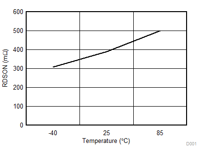
RDSON VM = 12 V
Figure 1. RDSON Across Temperature at 12 V
DRV10970 D003_SLVSCU7.gif
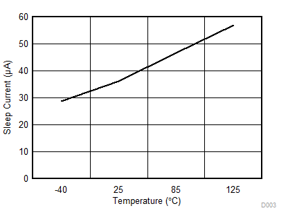
Sleep Current VM = 12 V
Figure 3. Sleep Current Across Temperature at 12 V
DRV10970 D005_SLVSCU7.gif
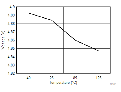
5-V Regulator VM = 12 V IL = 20 mA
Figure 5. VINT LDO Output Voltage Across Temperature,
VM = 12 V
DRV10970 D007_SLVSCU7.gif
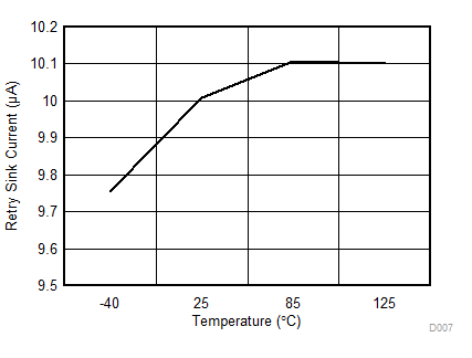
RETRY Sink Current VM = 12 V
Figure 7. Retry Sink Current at 12 V
DRV10970 D002_SLVSCU7.gif
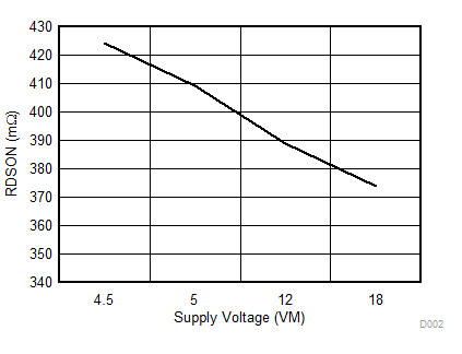
RDSON Temperature = 25°C
Figure 2. RDSON Across Voltage at 25°C
DRV10970 D004_SLVSCU7.gif
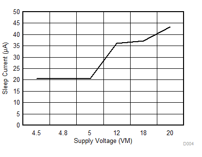
Sleep Current Temperature = 25°C
Figure 4. Sleep Current Across Voltage at 25°C
DRV10970 D006_SLVSCU7.gif
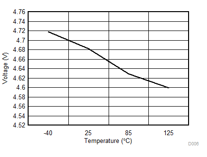
5-V Regulator VM = 5 V IL = 20 mA
Figure 6. VINT LDO Output Voltage Across Temperature,
VM = 5 V
DRV10970 D008_SLVSCU7.gif
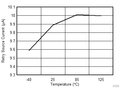
RETRY Source Current VM = 12 V
Figure 8. Retry Source Current at 12 V