SNOSDB6C December 2020 – March 2022 LMP7704-SP
PRODUCTION DATA
- 1 Features
- 2 Applications
- 3 Description
- 4 Revision History
- 5 Pin Configuration and Functions
- 6 Specifications
- 7 Detailed Description
- 8 Application and Implementation
- 9 Power Supply Recommendations
- 10Layout
- 11Device and Documentation Support
- 12Mechanical, Packaging, and Orderable Information
Package Options
Mechanical Data (Package|Pins)
- HBH|14
Thermal pad, mechanical data (Package|Pins)
Orderable Information
7.4.1 Precision Current Source
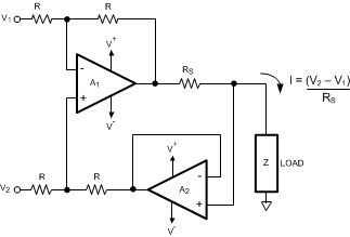
The LMP7704-SP can be used as a precision current source in many different applications. Figure 7-6 shows a typical precision current source. This circuit implements a precision, voltage-controlled current source. Amplifier A1 is a differential amplifier that uses the voltage drop across RS as the feedback signal. Amplifier A2 is a buffer that eliminates the error current from the load side of the RS resistor. In general, the circuit is stable as long as the closed-loop bandwidth of amplifier A2 is greater then the closed-loop bandwidth of amplifier A1. If A1 and A2 are the same type of amplifiers, then the feedback around A1 reduces bandwidth compared to A2.
 Figure 7-6 Precision Current Source
The equation for output current is derived as shown in Equation 4:

Solving for current I results in Equation 5:
