SLLSE57E April 2011 – March 2015 SN75DP130
PRODUCTION DATA.
- 1 Features
- 2 Applications
- 3 Description
- 4 Revision History
- 5 Description (continued)
- 6 Pin Configuration and Functions
- 7 Specifications
- 8 Parameter Measurement Information
- 9 Detailed Description
- 10Application and Implementation
- 11Power Supply Recommendations
- 12Layout
- 13Device and Documentation Support
- 14Mechanical, Packaging, and Orderable Information
Package Options
Mechanical Data (Package|Pins)
- RGZ|48
Thermal pad, mechanical data (Package|Pins)
- RGZ|48
Orderable Information
11 Power Supply Recommendations
11.1 SN75DP130 Power Sequencing
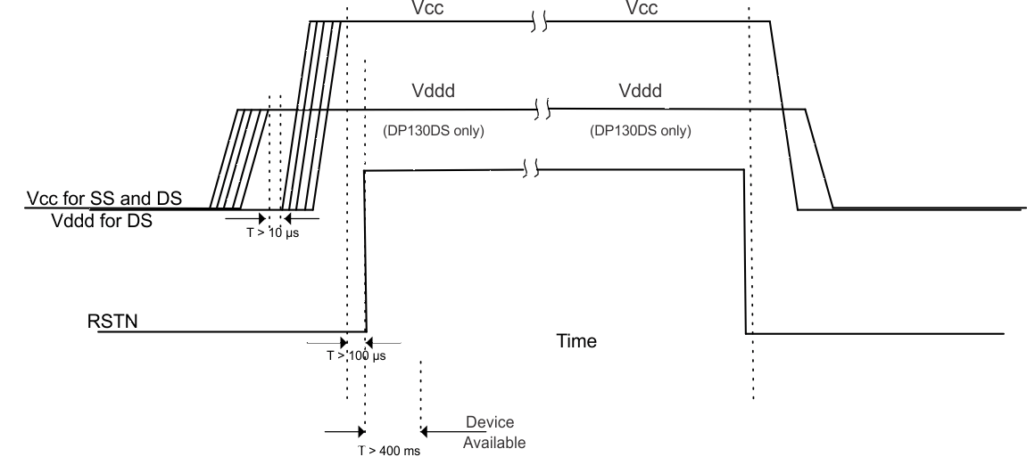
The following power-up and power-down sequences describe how the RSTN signal is applied to the SN75DP130. See Power Dissipation.
11.1.1 Power-Up Sequence:
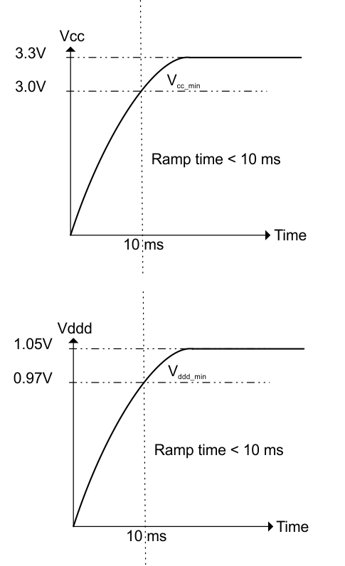
- Apply Vcc with less than a 10-ms ramp time for the SN75DP130 and for the SN75DP130, apply Vddd then Vcc (both having less than 10-ms ramp time) devices. Vddd must be asserted first and stable for greater than 10 µs before Vcc is applied.
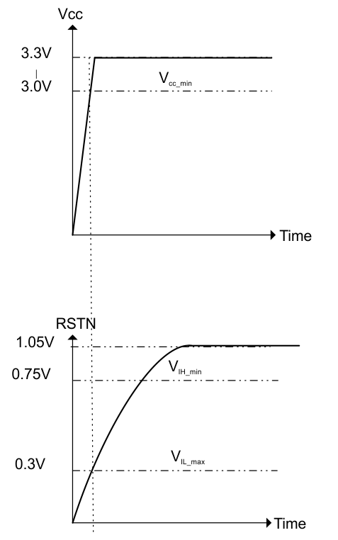
- RSTN must remain asserted until Vcc/Vddd voltage has reached minimum recommended operation for more than 100 µs.
- De-assert RSTN (Note: This RSTN is a 1.05-V interface and is internally connected to Vddd_dreg through a 150-kΩ resistor).
- Device will be available for operation approximately 400 ms after a valid reset.
11.1.2 Power-Down Sequence:
- Assert RSTN to the device.
- Remove Vcc and Vddd.
 Figure 35. VCC/VDDD Ramp Recommendation
 Figure 36. RSTN Voltage Thresholds
