SLUS658D July 2005 – June 2019 TPS40190
PRODUCTION DATA.
- 1 Features
- 2 Applications
- 3 Description
- 4 Revision History
- 5 Pin Configuration and Functions
- 6 Specifications
- 7 Detailed Description
- 8 Application and Implementation
- 9 Device and Documentation Support
- 10Mechanical, Packaging, and Orderable Information
Package Options
Refer to the PDF data sheet for device specific package drawings
Mechanical Data (Package|Pins)
- DRC|10
Thermal pad, mechanical data (Package|Pins)
- DRC|10
Orderable Information
7.3.2 Output Short Circuit Protection
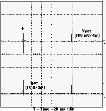
The short circuit detection in the TPS40190 is done by sensing the voltage drop across the high side FET when it is on. If the voltage drop across this FET exceeds the selected threshold in any given switching cycle, a counter counts up one count and the FET is turned off early. If the voltage drop across that FET does not exceed this threshold, the counter is decremented for that cycle and the FET is allowed to remain on for the normal pulse width commanded by the internal pulse width modulator. If the counter fills up (a count of 7) a fault condition is declared and the drivers turn both FETs off. After a timeout of approximately 95 ms, the controller attempts to restart. If a short circuit is still present at the output, the current ramps quickly up to the short-circuit threshold and another fault condition is declared. The device then waits 95 ms to attempt to restart again.
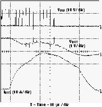
Typical waveforms during a short circuit event are shown in Figure 21 and Figure 22.
 Figure 21. Output Short Circuit Detected
(Nominal Threshold 25 A)
 Figure 22. Output Fault Hiccup Restart Timing
 The TPS40190 provides three selectable short circuit protection thresholds: 160 mV, 320 mV and 460 mV. The particular threshold is selected by connecting a resistor from COMP to GND. Table 1 gives the short circuit thresholds for corresponding resistors from COMP to GND. Note that since the TPS40190 measures the resistance from COMP to GND during a 2-ms window, the compensation network from COMP to FB should have a time constant significantly less than 1 ms or there can be issues detecting the resistance and setting the correct short circuit threshold. This network should have no DC path from COMP to FB.
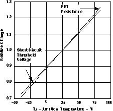
The short circuit detection threshold in the TPS40190 has some temperature compensation built in to help offset the high-side FET rise in resistance as its temperature rises. A typical FET has a resistance temperature coefficient of about 4500 ppm/°C. The temperature coefficient of the short circuit threshold is approximately 4200 ppm/°C. Figure 23 shows how the short circuit threshold increases with temperature to help compensate for the FET resistance increase. The relative FET resistance change is based on an estimate of a linear 4500 ppm/°C temperature coefficient. The effectiveness of this compensation depends on how tight the thermal coupling between the TPS40190 and the high-side FET is. Better thermal coupling between the TPS40190 and the high-side FET gives better compensation effectiveness.
 Figure 23. Relative Short Circuit Threshold Change vs Temperature
 Table 1. Short Circuit Threshold Voltage Selection
| SHORT CIRCUIT PROTECTION
RESISTANCE, RCOMP (kΩ) |
NOMINAL CURRENT LIMIT
VOLTAGE, VILIM (mV) |
|---|---|
| 10.8 to 13.2 | 460 |
| OPEN | 320 |
| 3.6 to 4.4 | 160 |
The range of short circuit current thresholds that can be expected is given by Equation 1 and Equation 2.


where
- ISCP is the short circuit current
- VILIM is the short circuit threshold
- RDS(on) is the channel resistance of the high-side MOSFET