SLUSBQ5D November 2013 – July 2016 UCC28180
PRODUCTION DATA.
- 1 Features
- 2 Applications
- 3 Description
- 4 Revision History
- 5 Description (Continued)
- 6 Pin Configuration and Functions
- 7 Specifications
-
8 Detailed Description
- 8.1 Overview
- 8.2 Functional Block Diagram
- 8.3
Feature Description
- 8.3.1 Soft Start
- 8.3.2 System Protection
- 8.3.3 VCC Undervoltage LockOut (UVLO)
- 8.3.4 Output Overvoltage Protection (OVP)
- 8.3.5 Open Loop Protection/Standby (OLP/Standby)
- 8.3.6 ISENSE Open-Pin Protection (ISOP)
- 8.3.7 ICOMP Open-Pin Protection (ICOMPP)
- 8.3.8 FAULT Protection
- 8.3.9 Output Overvoltage Detection (OVD), Undervoltage Detection (UVD) and Enhanced Dynamic Response (EDR)
- 8.3.10 Overcurrent Protection
- 8.3.11 Soft Overcurrent (SOC)
- 8.3.12 Peak Current Limit (PCL)
- 8.3.13 Current Sense Resistor, RISENSE
- 8.3.14 ISENSE Pin
- 8.3.15 Gate Driver
- 8.3.16 Current Loop
- 8.3.17 ISENSE and ICOMP Functions
- 8.3.18 Pulse Width Modulator
- 8.3.19 Control Logic
- 8.3.20 Voltage Loop
- 8.3.21 Output Sensing
- 8.3.22 Voltage Error Amplifier
- 8.3.23 Non-Linear Gain Generation
- 8.4 Device Functional Modes
-
9 Application and Implementation
- 9.1 Application Information
- 9.2
Typical Application
- 9.2.1 Design Requirements
- 9.2.2
Detailed Design Procedure
- 9.2.2.1 Current Calculations
- 9.2.2.2 Switching Frequency
- 9.2.2.3 Bridge Rectifier
- 9.2.2.4 Inductor Ripple Current
- 9.2.2.5 Input Capacitor
- 9.2.2.6 Boost Inductor
- 9.2.2.7 Boost Diode
- 9.2.2.8 Switching Element
- 9.2.2.9 Sense Resistor
- 9.2.2.10 Output Capacitor
- 9.2.2.11 Output Voltage Set Point
- 9.2.2.12 Loop Compensation
- 9.2.3 Application Curve
- 10Power Supply Recommendations
- 11Layout
- 12Device and Documentation Support . .
- 13Mechanical, Packaging, and Orderable Information
Package Options
Mechanical Data (Package|Pins)
- D|8
Thermal pad, mechanical data (Package|Pins)
Orderable Information
9 Application and Implementation
NOTE
Information in the following applications sections is not part of the TI component specification, and TI does not warrant its accuracy or completeness. TI’s customers are responsible for determining suitability of components for their purposes. Customers should validate and test their design implementation to confirm system functionality.
9.1 Application Information
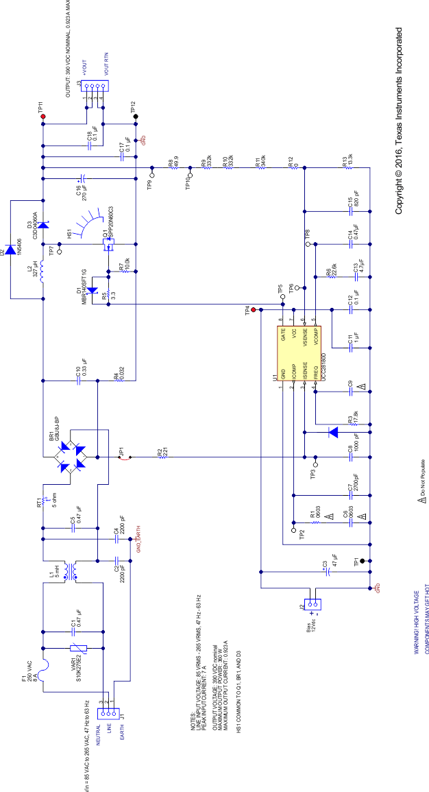
The UCC28180 is a switch-mode controller used in boost converters for power factor correction operating at a fixed frequency in continuous conduction mode. The UCC28180 requires few external components to operate as an active PFC pre-regulator. The operating switching frequency can be programmed from 18 kHz to 250 kHz simply by connecting the FREQ pin to ground through a resistor.
The internal 5-V reference voltage provides for accurate output voltage regulation over the typical world-wide 85-VAC to 265-VAC mains input range from zero to full output load. The usable system load ranges from 100 W to few kW.
Regulation is accomplished in two loops. The inner current loop shapes the average input current to match the sinusoidal input voltage under continuous inductor current conditions. Under light-load conditions, depending on the boost inductor value, the inductor current may go discontinuous but still meet Class-A/D requirements of IEC 61000-3-2 despite the higher harmonics. The outer voltage loop regulates the PFC output voltage by generating a voltage on VCOMP (dependent upon the line and load conditions) which determines the internal gain parameters for maintaining a low-distortion, steady-state, input-current wave shape.
9.2 Typical Application
9.2.1 Design Requirements
This example illustrates the design process and component selection for a continuous mode power factor correction boost converter utilizing the UCC28180. The pertinent design equations are shown for a universal input, 360-W PFC converter with an output voltage of 390 V.
Table 1. Design Goal Parameters
| PARAMETER | TEST CONDITIONS | MIN | TYP | MAX | UNIT | |
|---|---|---|---|---|---|---|
| INPUT CHARACTERISTICS | ||||||
| VIN | Input voltage | 85 | 265 | VAC | ||
| fLINE | Input frequency | 47 | 63 | Hz | ||
| IIN(peak) | Peak input current | VIN = VIN(min), IOUT = IOUT(max) |
7 | A | ||
| OUTPUT CHARACTERISTICS | ||||||
| VOUT | Output voltage | VIN(min) ≤ VIN ≤ VIN(max), fLINE(min) ≤ fLINE≤ fLINE(max), IOUT ≤ IOUT(max) |
379 | 390 | 402 | VDC |
| Line Regulation | VIN(min) ≤ VIN≤ VIN(max), IOUT = IOUT(max) |
5% | ||||
| Load Regulation | VIN = 115 VAC, fLINE = 60 Hz, IOUT(min) ≤ IOUT ≤ IOUT(max) |
5% | ||||
| VIN = 230 VAC, fLINE = 60 Hz, IOUT(min)≤ IOUT ≤ IOUT(max) |
5% | |||||
| IOUT | Output Load Current | VIN(min) ≤ VIN ≤ VIN(max)
fLINE(min) ≤ fLINE ≤ fLINE(max) |
0 | 0.923 | A | |
| POUT | Output Power | VIN(min) ≤ VIN ≤ VIN(max)
fLINE(min) ≤ fLINE ≤ fLINE(max) |
0 | 360 | W | |
| VRIPPLE(SW) | High frequency Output voltage ripple |
VIN = 115 VAC, fLINE = 60 Hz IOUT = IOUT(max) |
2.5 | 3.9 | VP-P | |
| VIN = 230 VAC, fLINE = 50 Hz IOUT = IOUT(max) |
2.5 | 3.9 | ||||
| VRIPPLE(f_LINE) | Line frequency Output voltage ripple |
VIN = 115 VAC, fLINE = 60 Hz, IOUT = IOUT(max) |
11.6 | 19.5 | VP-P | |
| VIN = 230 VAC, fLINE = 50 Hz, IOUT = IOUT(max) |
13.3 | 19.5 | ||||
| VOUT(OVP) | Output overvoltage protection | 425 | V | |||
| VOUT(UVP) | Output undervoltage protection | 370 | ||||
| CONTROL LOOP CHARACTERISTICS | ||||||
| fSW | Switching frequency | TJ = 25°C | 114 | 120 | 126 | kHz |
| f(CO) | Voltage Loop Bandwidth | VIN = 162 VDC, IOUT = 0.466 A |
8 | Hz | ||
| Voltage Loop Phase Margin | VIN = 162 VDC, IOUT = 0.466 A |
68 | ° | |||
| PF | Power Factor | VIN = 115 VAC, IOUT = IOUT(max) |
0.99 | |||
| THD | Total harmonic distortion | VIN = 115 VAC, fLINE = 60 Hz, IOUT = IOUT(max) |
4.3% | 10% | ||
| VIN = 230 VAC, fLINE = 50 Hz IOUT = IOUT(max) |
4% | 10% | ||||
| η | Full load efficiency | VIN = 115 VAC, fLINE = 60 Hz, IOUT = IOUT(max) |
94% | |||
| Ambient temperature | 25 | °C | ||||
9.2.2 Detailed Design Procedure
9.2.2.1 Current Calculations
The input fuse, bridge rectifier, and input capacitor are selected based upon the input current calculations. First, determine the maximum average output current, IOUT(max):


The maximum input RMS line current, IIN_RMS(max), is calculated using the parameters from Table 1 and the efficiency and power factor initial assumptions:


Based upon the calculated RMS value, the maximum input current, IIN (max), and the maximum average input current, IIN_AVG(max), assuming the waveform is sinusoidal, can be determined.


9.2.2.2 Switching Frequency
The UCC28180 switching frequency is user programmable with a single resistor on the FREQ pin to ground. For this design, the switching frequency, fSW, was chosen to be 120 kHz. Figure 30 (same as Figure 1) could be used to select the suitable resistor to program the switching frequency or the value can be calculated using constant scaling values of fTYP and RTYP. In all cases, fTYP is a constant that is equal to 65 kHz, RINT is a constant that is equal to 1 MΩ, and RTYP is a constant that is equal to 32.7 kΩ. Simply applying the calculation below yields the appropriate resistor that should be placed between FREQ and GND:


A typical value of 17.8 kΩ for the FREQ resistor results in a switching frequency of 118 kHz.
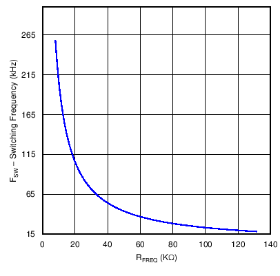 Figure 30. Frequency vs. RFREQ
9.2.2.3 Bridge Rectifier
The input bridge rectifier must have an average current capability that exceeds the input average current. Assuming a forward voltage drop, VF_BRIDGE, of 1 V across the rectifier diodes, BR1, the power loss in the input bridge, PBRIDGE, can be calculated:


Heat sinking will be required to maintain operation within the bridge rectifier’s safe operating area.
9.2.2.4 Inductor Ripple Current
The UCC28180 is a Continuous Conduction Mode (CCM) controller but if the chosen inductor allows relatively high-ripple current, the converter will be forced to operate in Discontinuous Mode (DCM) at light loads and at the higher input voltage range. High-inductor ripple current has an impact on the CCM/DCM boundary and results in higher light-load THD, and also affects the choices for the input capacitor, RSENSE and CICOMP values. Allowing an inductor ripple current, ΔIRIPPLE, of 20% or less will result in CCM operation over the majority of the operating range but requires a boost inductor that has a higher inductance value and the inductor itself will be physically large. As with all converter designs, decisions must be made at the onset in order to optimize performance with size and cost. In this design example, the inductor is sized in such a way as to allow a greater amount of ripple current in order to minimize space with the understanding that the converter operates in DCM at the higher input voltages and at light loads but optimized for a nominal input voltage of 115 VAC at full load. Although specifically defined as a CCM controller, the UCC28180 is shown in this application to meet the overall performance goals while transitioning into DCM at high-line voltage, at a higher load level.
9.2.2.5 Input Capacitor
The input capacitor must be selected based upon the input ripple current and an acceptable high frequency input voltage ripple. Allowing an inductor ripple current, ΔIRIPPLE, of 40% and a high frequency voltage ripple factor, ΔVRIPPLE_IN, of 7%, the maximum input capacitor value, CIN, is calculated by first determining the input ripple current, IRIPPLE, and the input voltage ripple, VIN_RIPPLE:


The recommended value for the input x-capacitor can now be calculated:


A standard value 0.33-µF Y2/X2 film capacitor is used.
9.2.2.6 Boost Inductor
Based upon the allowable inductor ripple current discussed above, the boost inductor, LBST, is selected after determining the maximum inductor peak current, IL_PEAK:


The minimum value of the boost inductor is calculated based upon the acceptable ripple current, IRIPPLE, at a worst case duty cycle of 0.5:


The recommended minimum value for the boost inductor assuming a 40% ripple current is 321 µH; the actual value of the boost inductor that will be used is 327 µH. With this actual value used, the actual resultant inductor current ripple will be:


The duty cycle is a function of the rectified input voltage and will be continuously changing over the half line cycle. The duty cycle, DUTY(max), can be calculated at the peak of the minimum input voltage:


9.2.2.7 Boost Diode
The diode losses are estimated based upon the forward voltage drop, VF, at 125°C and the reverse recovery charge, QRR, of the diode. Using a silicon carbide Schottky diode, although more expensive, will essentially eliminate the reverse recovery losses and result in less power dissipation:


This output diode should have a blocking voltage that exceeds the output over voltage of the converter and be attached to an appropriately sized heat sink.
9.2.2.8 Switching Element
The MOSFET/IGBT switch will be driven by a GATE output that is clamped at 15.2 V for VCC bias voltages greater than 15.2 V. An external gate drive resistor is recommended to limit the rise time and to dampen any ringing caused by the parasitic inductances and capacitances of the gate drive circuit; this will also help in meeting any EMI requirements of the converter. The design example uses a 3.3-Ω resistor; the final value of any design is dependent upon the parasitic elements associated with the layout of the design. To facilitate a fast turn off, a standard 40-V, 1-A Schottky diode is placed anti-parallel with the gate drive resistor. A 10-kΩ resistor is placed between the gate of the MOSFET/IGBT and ground to discharge the gate capacitance and protect from inadvertent dv/dt triggered turn-on.
The conduction losses of the switch MOSFET, in this design are estimated using the RDS(on) at 125°C, found in the device data sheet, and the calculated drain to source RMS current, IDS_RMS:


The switching losses are estimated using the rise time, tr, and fall time, tf, of the MOSFET gate, and the output capacitance losses.


Total FET losses

The MOSFET requires an appropriately sized heat sink.
9.2.2.9 Sense Resistor
To accommodate the gain of the non-linear power limit, the sense resistor, RSENSE, is sized such that it triggers the soft over current at 10% higher than the maximum peak inductor current using the minimum soft over current threshold of the ISENSE pin, VSOC, of ISENSE equal to 0.265 V.


The power dissipated across the sense resistor, PRSENSE, must be calculated:


The peak current limit, PCL, protection feature is triggered when current through the sense resistor results in the voltage across RSENSE to be equal to the VPCL threshold. For a worst case analysis, the maximum VPCL threshold is used:


To protect the device from inrush current, a standard 220-Ω resistor, RISENSE, is placed in series with the ISENSE pin. A 1000-pF capacitor is placed close to the device to improve noise immunity on the ISENSE pin.
9.2.2.10 Output Capacitor
The output capacitor, COUT, is sized to meet holdup requirements of the converter. Assuming the downstream converters require the output of the PFC stage to never fall below 300 V, VOUT_HOLDUP(min), during one line cycle, tHOLDUP = 1/fLINE(min), the minimum calculated value for the capacitor is:


It is advisable to de-rate this capacitor value by 10%; the actual capacitor used is 270 µF.
Verifying that the maximum peak-to-peak output ripple voltage will be less than 5% of the output voltage ensures that the ripple voltage will not trigger the output over-voltage or output under-voltage protection features of the controller. If the output ripple voltage is greater than 5% of the regulated output voltage, a larger output capacitor is required. The maximum peak-to-peak ripple voltage, occurring at twice the line frequency, and the ripple current of the output capacitor is calculated:


The required ripple current rating at twice the line frequency is equal to:


There is a high frequency ripple current through the output capacitor:


The total ripple current in the output capacitor is the combination of both and the output capacitor must be selected accordingly:


9.2.2.11 Output Voltage Set Point
For low power dissipation and minimal contribution to the voltage set point, it is recommended to use 1 MΩ for the top voltage feedback divider resistor, RFB1. Multiple resistors in series are used due to the maximum allowable voltage across each. Using the internal 5-V reference, VREF, the bottom divider resistor, RFB2, is selected to meet the output voltage design goals.


A standard value 13-kΩ resistor for RFB2 results in a nominal output voltage set point of 391 V.
An output over voltage is detected when the output voltage exceeds its nominal set-point level by 5%, as measured when the voltage at VSENSE is 105% of the reference voltage, VREF. At this threshold, the enhanced dynamic response (EDR) is triggered and the non-linear gain to the voltage error amplifier will increase the transconductance to VCOMP and quickly return the output to its normal regulated value. This EDR threshold occurs when the output voltage reaches the VOUT(ovd) level:


In the event of an extreme output over voltage event, the GATE output will be disabled if the output voltage exceeds its nominal set-point value by 9%. The output voltage, VOUT(ovp), at which this protection feature is triggered is calculated as follows:

An output under voltage is detected when the output voltage falls below 5% below its nominal set-point as measured when the voltage at VSENSE is 95% of the reference voltage, VREF:


A small capacitor on VSENSE must be added to filter out noise. Limit the value of the filter capacitor such that the RC time constant is limited to approximately 10 µs so as not to significantly reduce the control response time to output voltage deviations.

The closest standard value of 820 pF was used on VSENSE for a time constant of 10.66 µs.
9.2.2.12 Loop Compensation
The current loop is compensated first by determining the product of the internal loop variables, M1M2, using the internal controller constants K1 and KFQ. Compensation is optimized maximum load and nominal input voltage, 115 VAC is used for the nominal line voltage for this design:

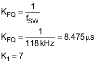

The VCOMP operating point is found on the following chart, M1M2 vs. VCOMP. Once the M1M2 result is calculated above, find the resultant VCOMP voltage at that operating point to calculate the individual M1 and M2 components.
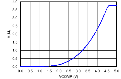 Figure 31. M1M2 vs. VCOMP
For the given M1M2 of 0.751 V/µs, the VCOMP approximately equal to 3 V, as shown in Figure 31.
The individual loop factors, M1 which is the current loop gain factor, and M2 which is the voltage loop PWM ramp slope, are calculated using the following conditions:
The M1 non-linear current loop gain factor follows the following identities:
 if VCOMP < 1 V
 if 1 V < VCOMP < 2 V
 if 2 V < VCOMP < 4.5 V
 if 4.5 V < VCOMP < 5 V
In this example, according to the chart in Figure 31, VCOMP is approximately equal to 3 V, so M1 is calculated to be approximately equal to 0.366:

The M2 non-linear PWM ramp slope will obey the following relationships:
 if VCOMP ≤ 0.5 V
 if 0.5 V ≤ VCOMP ≤ 4.6 V
 if 4.6 V ≤ VCOMP ≤ 5 V
In this example, with VCOMP approximately equal to 3 V, M2 equals 1.388 V/µs:

Verify that the product of the individual gain factors, M1 and M2, is approximately equal to the M1M2 factor determined above, if not, iterate the VCOMP value and recalculate M1M2

The product of M1 and M2 is within 1% of the M1M2 factor previously calculated:


If more accuracy was desired, iteration results in a VCOMP value of 3.004 V where M1M2 and M1 x M2 are both equal to 0.751 V/µs.
The non-linear gain variable, M3, can now be calculated:
 if VCOMP < 5 V
 if 0.5 V < VCOMP < 1 V
 if 1 V < VCOMP < 2 V
 if 2 V < VCOMP < 4.5 V
 if 4.5 V < VCOMP < 4.6 V
 if 4.6 V < VCOMP < 5 V
In this example, using 3.004 V for VCOMP for a more precise calculation, M3 calculates to 1.035 V/µs:

For designs that allow a high inductor ripple current, the current averaging pole, which functions to flatten out the ripple current on the input of the PWM comparator, should be at least decade before the converter switching frequency. Analysis on the completed converter may be needed to determine the ideal compensation pole for the current averaging circuit as too large of a capacitor on ICOMP will add phase lag and increase iTHD where as too small of an ICOMP capacitor will result in not enough averaging and an unstable current averaging loop. The frequency of the current averaging pole, fIAVG, is chosen to be at approximately 5 kHz for this design as the current ripple factor, ∆IRIPPLE, was chosen at the onset of the design process to be 40%, which is large enough to force DCM operation and result in relatively high inductor ripple current. The required capacitor on ICOMP, CICOMP, for this is determined using the transconductance gain, gmi, of the internal current amplifier:

A standard value 2700-pF capacitor for CICOMP results in a current averaging pole frequency of 4.314 kHz.

The transfer function of the current loop can be plotted:


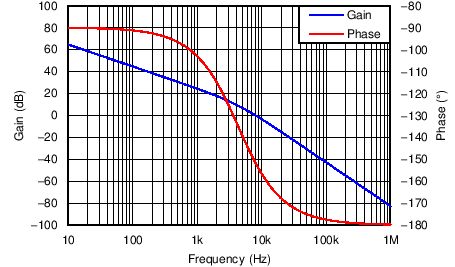 Figure 32. Bode Plot of the Current Averaging Circuit
The voltage transfer function, GVL(f) contains the product of the voltage feedback gain, GFB, and the gain from the pulse width modulator to the power stage, GPWM_PS, which includes the pulse width modulator to power stage pole, fPWM_PS. The plotted result is shown in Figure 32.
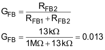
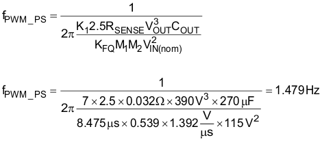
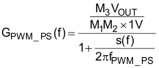

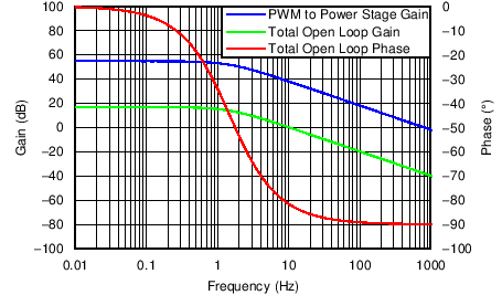 Figure 33. Bode Plot of the Open Voltage Loop without Error Amplifier
The voltage error amplifier is compensated with a zero, fZERO, at the fPWM_PS pole and a pole, fPOLE, placed at 20 Hz to reject high frequency noise and roll off the gain amplitude. The overall voltage loop crossover, fV, is desired to be at 10 Hz. The compensation components of the voltage error amplifier are selected accordingly.


From Figure 33, the gain of the voltage transfer function at 10 Hz is approximately 0.081 dB. Estimating that the parallel capacitor, CVCOMP_P, is much smaller than the series capacitor, CVCOMP, the unity gain will be at fV, and the zero will be at fPWM_PS, the series compensation capacitor is determined:


The capacitor for VCOMP must have a voltage rating that is greater than the absolute maximum voltage rating of the VCOMP pin, which is 7 V. The readily available standard value capacitor that is rated for at least 10 V in the package size that would fit the application was 4.7 µF and this is the value used for CVCOMP in this design example.
RVCOMP is calculated using the actual CVCOMP capacitor value.


A 22.6-kΩ resistor is used for RVCOMP.


A 0.47-µF capacitor is used for CVCOMP_P.
The total closed loop transfer function, GVL_total, contains the combined stages and is plotted in Figure 34.


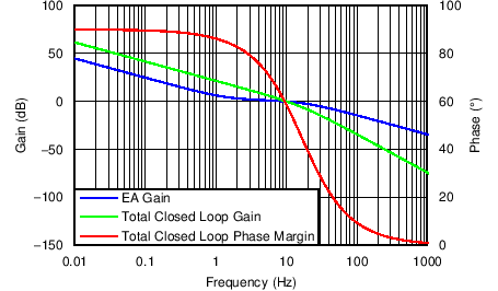 Figure 34. Closed Loop Voltage Bode Plot
9.2.3 Application Curve
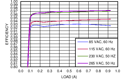 Figure 35. UCC28180EVM-573 Efficiency
 (As a Function of Line Voltage and Load Current)
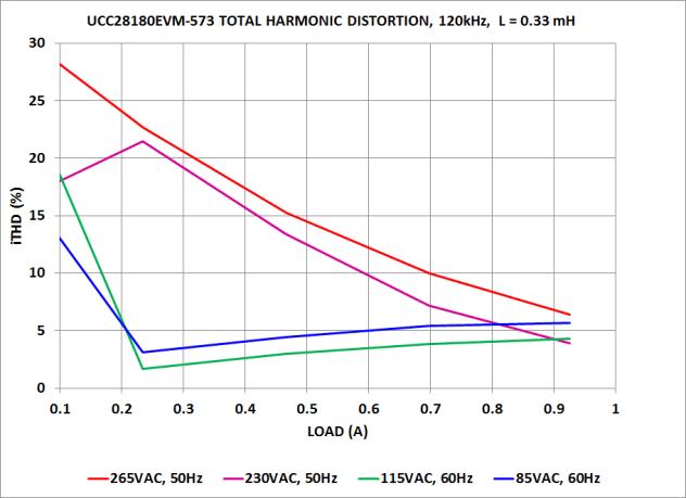 Figure 37. UCC28180EVM-573 Total Harmonic Distortion
 (As a Function of Line Voltage and Load Current)
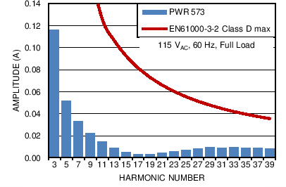 Figure 39. UCC28180EVM-573 Current Harmonics,
 (115-VAC, 60-Hz Input, Full Load, Without the Fundamental)
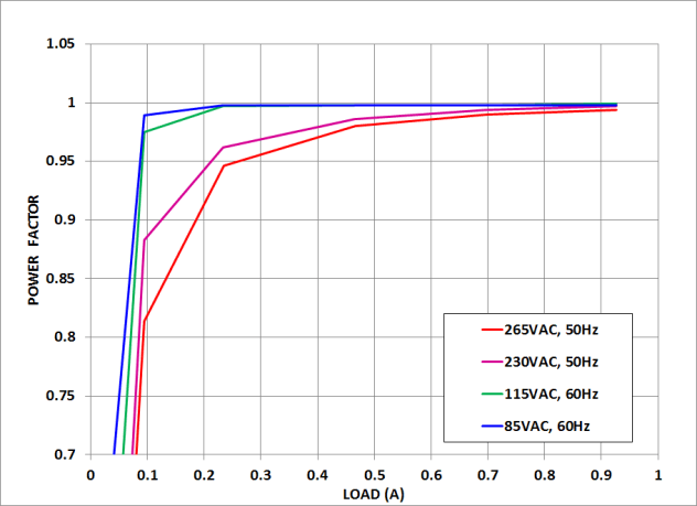 Figure 36. UCC28180EVM-573 Power Factor
 (As a Function of Line Voltage and Load Current)
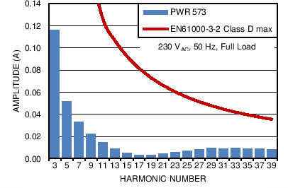 Figure 38. UCC28180EVM-573 Current Harmonics,
 (230-VAC, 50-Hz Input, Full Load, Without the Fundamental)
