SNOSCZ7B December 2015 – April 2024 LDC0851
PRODUCTION DATA
- 1
- 1 Features
- 2 Applications
- 3 Description
- 4 Pin Configuration and Functions
- 5 Specifications
- 6 Detailed Description
- 7 Application and Implementation
- 8 Device and Documentation Support
- 9 Revision History
- 10Mechanical, Packaging, and Orderable Information
パッケージ・オプション
メカニカル・データ(パッケージ|ピン)
- DSG|8
サーマルパッド・メカニカル・データ
- DSG|8
発注情報
6.3.1 Basic Operation Mode
The LDC0851 is configured for Basic Operation mode when the ADJ pin is tied to ground. Two identical coils should be used for LSENSE and LREF. The switching point occurs when the inductances of both coils are equal. Basic Operation mode can be used for a wide variety of applications including event counting, sliders, or proximity sensing. An example showing gear tooth counting can be found in section Event Counting.
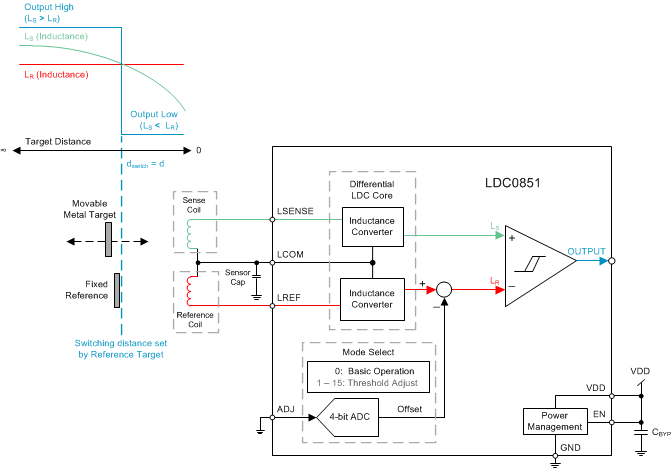
For proximity sensing the switching point can be set by placing a conductive target at a fixed distance from the reference coil as shown in Figure 6-1. The output will switch when a conductive target approaches LSENSE and reaches the same distance set by the fixed reference target. For reliable and repeatable switching it is recommended to place the reference target at a distance less than 40% of the coil diameter from the reference coil.
 Figure 6-1 Basic Operation Mode Diagram for Distance Sensing With Reference Target
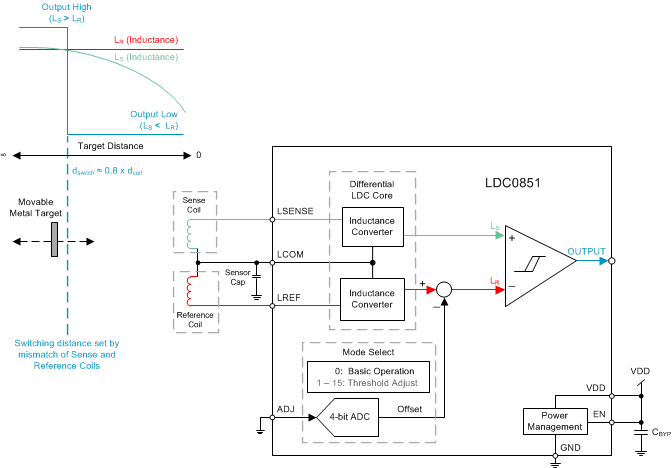
In some systems adding a reference target at a fixed height to set the switching distance is not feasible. Therefore to set the switching distance a small amount of mismatch between the sense and reference coils can be introduced. To achieve the maximum switching distance the reference inductance should be approximately 0.4% less than the sense inductance as shown in Figure 6-2 below. The 0.4% mismatch will ensure that the output will switch off when the target is removed.
 Figure 6-2 Basic Operation Mode Diagram for Distance Sensing With Mismatched Coils