JAJS012J October 2004 – November 2018 TPS75003
PRODUCTION DATA.
- 1 特長
- 2 アプリケーション
- 3 概要
- 4 改訂履歴
- 5 Pin Configuration and Functions
- 6 Specifications
-
7 Detailed Description
- 7.1 Overview
- 7.2 Functional Block Diagram
- 7.3
Feature Description
- 7.3.1 Operation (Buck Controllers)
- 7.3.2 Enable (Buck Controllers)
- 7.3.3 UVLO (Buck Controllers)
- 7.3.4 Current Limit (Buck Controllers)
- 7.3.5 Short-Circuit Protection (Buck Controllers)
- 7.3.6 Soft-Start (Buck Controllers)
- 7.3.7 LDO Operation
- 7.3.8 Internal Current Limit (LDO)
- 7.3.9 Enable Pin (LDO)
- 7.3.10 Dropout Voltage (LDO)
- 7.3.11 Transient Response (LDO)
- 7.3.12 Thermal Protection (LDO)
- 7.3.13 Power Dissipation (LDO)
-
8 Application and Implementation
- 8.1 Application Information
- 8.2
Typical Application
- 8.2.1 Design Requirements
- 8.2.2
Detailed Design Procedure
- 8.2.2.1 Input Capacitor CIN1, CIN2 Selection (Buck Controllers)
- 8.2.2.2 Inductor Value Selection (Buck Controllers)
- 8.2.2.3 External PMOS Transistor Selection (Buck Controllers)
- 8.2.2.4 Diode Selection (Buck Controllers)
- 8.2.2.5 Output Capacitor Selection (Buck Controllers)
- 8.2.2.6 Output Voltage Ripple Effect on VOUT (Buck Controllers)
- 8.2.2.7 Soft-Start Capacitor Selection (Buck Controllers)
- 8.2.2.8 Output Voltage Setting Selection (Buck Controllers)
- 8.2.2.9 Input Capacitor Selection (LDO)
- 8.2.2.10 Output Capacitor Selection (LDO)
- 8.2.2.11 Soft-Start Capacitor Selection (LDO)
- 8.2.2.12 Setting Output Voltage (LDO)
- 8.2.3 Application Curves
- 9 Power Supply Recommendations
- 10Layout
- 11デバイスおよびドキュメントのサポート
- 12メカニカル、パッケージ、および注文情報
パッケージ・オプション
メカニカル・データ(パッケージ|ピン)
- RHL|20
サーマルパッド・メカニカル・データ
- RHL|20
発注情報
8.2.2.7 Soft-Start Capacitor Selection (Buck Controllers)
The soft-start for BUCK1 and BUCK2 is not intended to be a precision function. However, the startup time (from a positive transition on Enable to VOUT reaching its final value) has a linear relationship to CSS up to approximately 800pF, which results in a startup time of approximately 4ms. Above this value of CSS, the variation in start-up time increases rapidly. This variation can occur from unit to unit and even between the two BUCK controllers in one device. Therefore, do not depend on the soft-start feature for sequencing multiple supplies if values of CSS greater than 800pF are used.
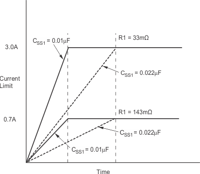
BUCK1 is discussed in this section; it is identical to BUCK2. Soft-start is implemented on the buck controllers by ramping current limit from 0 to its target value (set by R1) over a user-defined time. This time is set by the external soft-start cap connected to pin SS1. If SS1 is left open, a small on-chip capacitor will provide a current limit ramp time of approximately 250μs. Figure 19 shows the effects of R1 and SS1 on the current limit start-up ramp.
 Figure 19. Effects of CSS1 and R1 on Current Ramp Limit
 This soft-start current limit ramp can be used to provide inrush current control or output voltage ramp control. While the current limit ramp can be easily understood by looking at Figure 19, the output voltage ramp is a complex function of many variables. The dominant variables in this process are VOUT1, CSS1, IOUT1, and R1. Less important variables are VIN1 and L1.
The best way to set a target start-up time is through bench measurement under target conditions, adjusting CSS1 to get the desired startup profile. To stay above a minimum start-up time, set the nominal start-up time to approximately five times the minimum. To stay below a maximum time, set the nominal start-up time at one-fifth of the maximum. Fastest start-up times occur at maximum VIN1, with minimum VOUT1, L1, COUT1, CSS1, and IOUT1. Slowest start-up times occur under opposite conditions.
Refer to Figure 21 to Figure 25 for characterization curves showing how the start-up profile is affected by these critical parameters.