JAJSEW6B February 2018 – February 2024 UCC21222
PRODUCTION DATA
- 1
- 1 特長
- 2 アプリケーション
- 3 概要
- 4 Pin Configuration and Functions
-
5 Specifications
- 5.1 Absolute Maximum Ratings
- 5.2 ESD Ratings
- 5.3 Recommended Operating Conditions
- 5.4 Thermal Information
- 5.5 Power Ratings
- 5.6 Insulation Specifications
- 5.7 Safety-Related Certifications
- 5.8 Safety-Limiting Values
- 5.9 Electrical Characteristics
- 5.10 Switching Characteristics
- 5.11 Thermal Derating Curves
- 5.12 Typical Characteristics
- 6 Parameter Measurement Information
- 7 Detailed Description
-
8 Application and Implementation
- 8.1 Application Information
- 8.2
Typical Application
- 8.2.1 Design Requirements
- 8.2.2
Detailed Design Procedure
- 8.2.2.1 Custom Design With WEBENCH® Tools
- 8.2.2.2 Designing INA/INB Input Filter
- 8.2.2.3 Select Dead Time Resistor and Capacitor
- 8.2.2.4 Select External Bootstrap Diode and its Series Resistor
- 8.2.2.5 Gate Driver Output Resistor
- 8.2.2.6 Estimating Gate Driver Power Loss
- 8.2.2.7 Estimating Junction Temperature
- 8.2.2.8 Selecting VCCI, VDDA/B Capacitor
- 8.2.2.9 Application Circuits with Output Stage Negative Bias
- 8.2.3 Application Curves
- 9 Power Supply Recommendations
- 10Layout
- 11Device and Documentation Support
- 12Revision History
- 13Mechanical, Packaging, and Orderable Information
3 概要
UCC21222 は、プログラミング可能なデッドタイムを備えた絶縁型デュアル チャネル ゲート ドライバです。ピーク電流はソース 4A、シンク 6A で、パワー MOSFET、IGBT、GaN トランジスタを駆動するように設計されています。
デバイスは、2 つのローサイド ドライバ、2 つのハイサイド ドライバ、または 1 つのハーフ ブリッジ ドライバとして構成可能です。5ns の遅延マッチング性能により、内部貫通電流のリスクを伴わずに、2 つの出力を並列化して 2 倍の駆動力で重負荷条件に対応できます。
入力側は、3.0kVRMS の絶縁バリアによって 2 つの出力ドライバと分離されており、同相過渡耐性 (CMTI) は 100V/ns 以上です。
抵抗によるデッドタイムのプログラミングが可能なため、システムの制約に合わせてデッドタイムを調整することにより、効率を高め、出力のオーバーラップを防止できます。その他の保護機能として、DIS をHigh に設定した場合に 2 つの出力を同時にシャットダウンするディスエーブル機能、5ns 未満の入力過渡を除去する内蔵グリッチ除去フィルタ、入力 / 出力ピンでの 200ns にわたる最大 -2V のスパイクに対応する負電圧処理機能があります。すべての電源が UVLO 機能を備えています。
製品情報
| 部品番号(1) | パッケージ | 本体サイズ (公称) |
|---|---|---|
| UCC21222 | D (SOIC 16) | 9.9mm × 3.91mm |
(1) 供給されているすべてのパッケージについては、セクション 13 を参照してください。
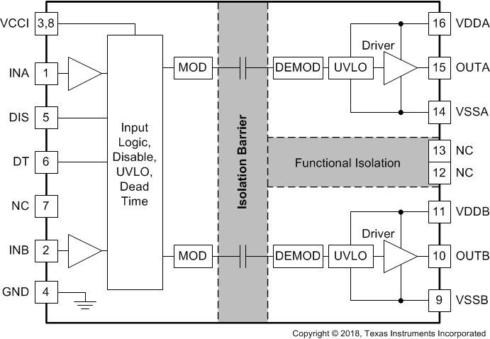
 機能ブロック図