DLPA027B January 2024 – April 2024 DLP500YX , DLP5500 , DLP6500FLQ , DLP6500FYE , DLP650LNIR , DLP670S , DLP7000 , DLP7000UV , DLP9000 , DLP9000X , DLP9000XUV , DLP9500 , DLP9500UV
2.2 Bulk Mirror to Silicon Delta (ΔTBULK_MIRROR-TO-SILICON)
Absorbed heat must be transferred from the DMD mirror to the underlying silicon. This is true in a CW application as well as a pulsed application. Normally the temperature rise of the bulk mirror above the silicon in CW applications is small, but in pulsed applications, the peak optical power can be much higher than the average power. This results in a rise and fall of the bulk mirror temperature with each pulse. The bulk mirror temperature rise is defined by Equation 3.
Where:
= mirror temperature at time = t
= final mirror temperature at t = ∞ (steady-state)
= initial mirror temperature at t = 0
= thermal time constant of the mirror (R × C) [Table 2-1]
Where:
= total incident power per mirror [incident power density × (mirror pitch)2]
= fill factor of mirror array (on-state calculates highest temperature) [Table 2-2]
= mirror reflectivity [Figure 2-1, Figure 2-2, Figure 2-3]
| Pixel [μm] | RMIRROR-TO-SILICON [ºC/W] | CMIRROR [J/ºC] | = R*C [μs] |
|---|---|---|---|
| 5.4 (12º) | 7.63 x 10⁵ | 1.14 x 10⁻¹¹ | 8.70 |
| 5.4 (17º) | 9.54 x 10⁵ | 1.14 x 10⁻¹¹ | 10.88 |
| 7.56, 7.60, 7.637 | 4.47 x 10⁵ | 2.57 x 10⁻¹¹ | 11.49 |
| 9.0 | 4.53 x 10⁵ | 4.21 x 10⁻¹¹ | 19.07 |
| 10.8 | 3.39 x 10⁵ | 9.52 x 10⁻¹¹ | 32.27 |
| 13.68 | 2.52 x 10⁵ | 1.53 x 10⁻¹⁰ | 38.56 |
The thermal time constant of the mirror, , is defined as RMIRROR ✕ CMIRROR
Where:
RMIRROR is the thermal resistance from the mirror to the silicon
CMIRROR is the thermal capacitance of the mirror
In Table 2-1, R was calculated using a finite element model of the pixel superstructure and distance between the mirror and the silicon. C was calculated as ρVCp where;
ρ = density of the aluminum mirror
V = volume of the aluminum mirror
Cp = specific heat of the aluminum mirror
Therefore, is different for each mirror pitch
| FFMIRROR | |||
|---|---|---|---|
| Pixel [μm] | On-state | Off-state | Illumination Angle [Degrees] |
| 5.4 (12º) | 0.901 | 0.720 | 24 |
| 5.4 (17º) | 0.911 | 0.765 | 34 |
| 7.56, 7.60 | 0.931 | 0.724 | 24 |
| 7.637 | 0.936 | 0.728 | 24 |
| 9.0 | 0.967 | 0.600 | 29 |
| 10.8 | 0.931 | 0.726 | 24 |
| 13.68 | 0.950 | 0.728 | 24 |
- 12º tilt = ƒ/2.4
- 14.5º tilt = ƒ/2.0
- 17º tilt = ƒ/1.7
") Figure 2-1 Mirror Reflectivity versus Wavelength (UV)
Figure 2-1 Mirror Reflectivity versus Wavelength (UV)") Figure 2-2 Mirror Reflectivity versus Wavelength (Visible)
Figure 2-2 Mirror Reflectivity versus Wavelength (Visible)") Figure 2-3 Mirror Reflectivity versus Wavelength (Near-Infrared)
Figure 2-3 Mirror Reflectivity versus Wavelength (Near-Infrared)| tpulse | toff | Mirror Heating Condition | Temperature Plot vs. Time |
|---|---|---|---|
| > | > | Mirror fully heats and cools during each pulse | 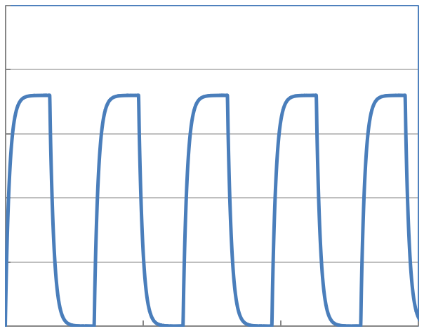 |
| > | < | Mirror fully heats and partially cools during each pulse | 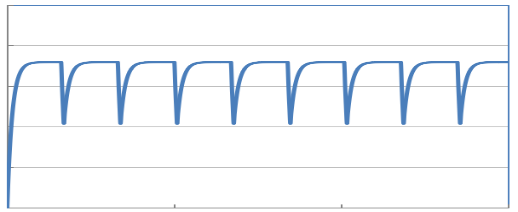 |
| < | > | Mirror partially heats, then fully cools during each pulse | 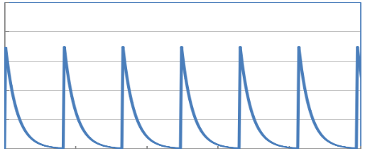 |
| < | < | Mirror partially heats and partially cools during each pulse until finally reaching steady-state after many pulses | 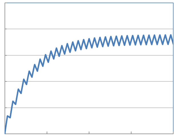 |
There are several possibilities of the resulting transient response of the mirror depending on the duration of tpulse and toff relative to the thermal time constant of the mirror. These possibilities are shown in Table 2-3.
 Figure 2-4 Pulse Parameters