DLPU082C August 2021 – March 2024 DLPC7540
- 1
- Abstract
- Trademarks
- 1 Scope
- 2 References
- 3 Acronyms
- 4 System Boot
- 5 System Status
- 6 Version
- 7 Power Modes
- 8 Display Modes
- 9 Source Detection and Configuration
- 10Internal Sources
- 11Display Formatting
- 12Image Processing
-
13Warping
- 13.1 Control Point Table
- 13.2 Manual Warp Table
- 13.3 Table Constraints
- 13.4 Example Warp Table
- 13.5
Manual Warping Commands
- 13.5.1 CMD_SetManualWarpControlPoints [Command ID: 0x35, Destination: 4]
- 13.5.2 CMD_GetManualWarpControlPoints [Command ID: 0x35, Destination: 4]
- 13.5.3 CMD_WriteManualWarpTable [Opcode: 0x34, Destination: 4]
- 13.5.4 CMD_ReadManualWarpTable [Opcode: 0x34, Destination: 4]
- 13.5.5 CMD_ConfigureSmoothWarp [Command ID: 0x38, Destination: 4]
- 13.5.6 CMD_ApplyManualWarping [Command ID: 0x36, Destination: 4]
- 13.6 Optical (Lens) Distortion Correction
-
14Introduction to Blending
- 14.1 Blend Map Control Points
- 14.2 Blend Map Gain Values
- 14.3 Blend Map Offset Value
- 14.4 Constraints
- 14.5
Manual Blending Commands
- 14.5.1 CMD_EnableEdgeBlending [Command ID: 0x2F]
- 14.5.2 CMD_SetBlendMapControlPoints [Opcode: 0x2E]
- 14.5.3 CMD_ GetBlendMapControlPoints [Command ID: 0x2E]
- 14.5.4 CMD_SetBlendMapGainValues [Command ID: 0x2B]
- 14.5.5 CMD_ GetBlendMapGainValues [Command ID: 0x2B]
- 14.5.6 CMD_ SetBlendMapOffsetValues [Command ID: 0x2D]
- 14.5.7 CMD_ GetBlendMapOffsetValues [Command ID: 0x2D]
- 14.5.8 CMD_ApplyBlendMap [Command ID: 0x2C]
- 14.6 Manual Blending Application Commands
- 14.7 Cropping of Input Image for Blending Setup
- 14.8 Storing Edge Blend Configuration in EEPROM
- 14.9 Storing in EEPROM or Secondary Flash
- 14.10 Manual Blending GUI in Control Program
- 15Illumination Control
- 16Peripherals
- 17Interface Protocol
- 18Command Protocol
- 19Auto-Initialization Batch File
- 20Command Descriptions
- 21System Commands
- Revision History
14.6 Manual Blending Application Commands
There are two modes of blending available through manual blending application commands: 2D Luminance, and Simple 1D RGB.
Simple 1D RGB mode is designed to support simple blending use cases where no warping is required. This implies that the blended projector display areas must be overlapped orthogonally. Any warping causes visual artifacts. Gains and offsets are manually configured visually by the user for each projector to match black and white levels between projectors. This mode supports controlling the RGB gain for matching white color and luminance between projectors. The gain automatically is linearly ramped from the full value at the beginning of the overlapping region to zero at the end to create a smooth transition between projectors. Also supported are RGB offsets for the non-overlapping region, overlapping regions, and the regions when the POM from the adjacent projectors overlap. The overlap amount is specified by the user, and POM width is automatically detected through the hardware configuration.
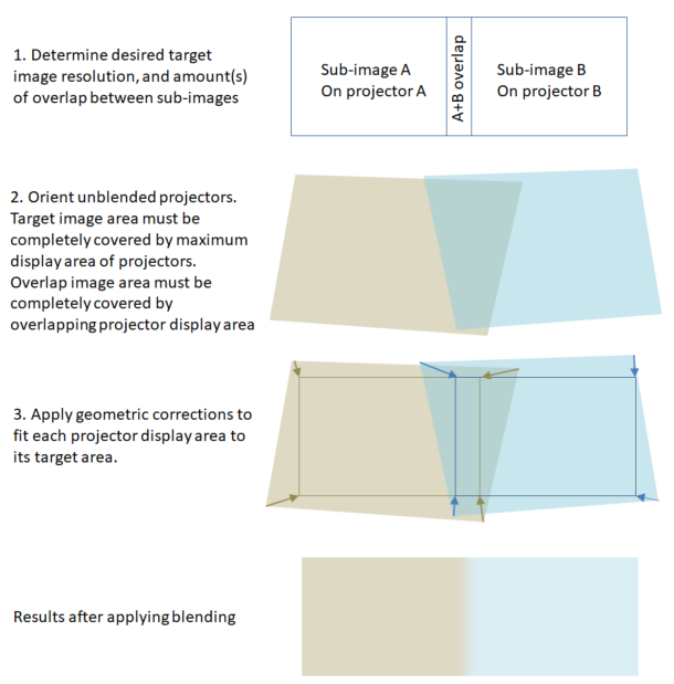
2D Luminance blending supports the blending of a rectangular grid of N×M projectors up to 27 in total. This mode allows for warping to be used with blending as follows (illustration of two projector case):
For Simple 1D RGB mode, warping is not allowed. Therefore, the projectors must be overlapped and orthogonally aligned. The overlaps between all projectors in the horizontal (X) direction and vertical direction (Y) are configurable. The gain and offset values for the blending map for any given projector within the blending system is directly determined by the user for Simple 1D RGB mode. For 2D Luminance mode, gain and offset are calculated from:
- The full-on white levels of all projectors in the blending system
- The full-off black levels of all projectors in the blending system
- The number of pixels of vertical and horizontal overlaps between adjacent projectors
- Geometric correction information
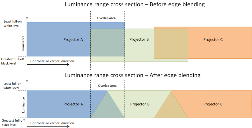
The gain and offset values in the blending map makes sure that there is a single luminance range across all projectors, and that there is a ramped transition from one projector to another within the overlapping area.
Geometric correction is available via keystone corners only, which has the implication that the warping can only accommodate planar surfaces.
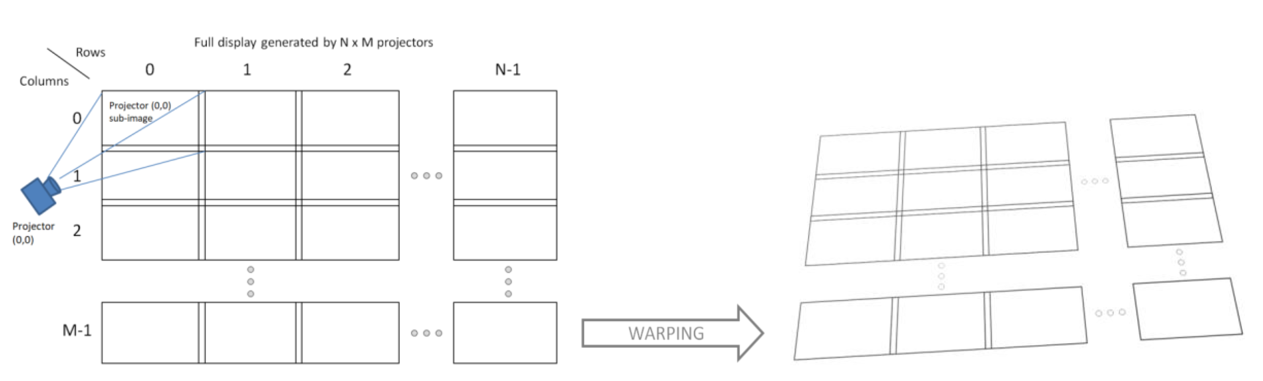
An example Python script for 2D Luminance mode is given illustrating a 3×3 blended projector system. The script is usable within DLP control program:
from dlpc754x.commands import *
from System.Threading import *
#Enable edge blending
WriteEnableEdgeBlending(1)
#Enable manual warping
WriteApplyManualWarping(1)
#Assign number of projectors in system
NumProjectorsColumns = 3
NumProjectorsRows = 3
#Assign index of self projector
SelfProjectorColumn = 1
SelfProjectorRow = 1
#Assign white and black luminance levels for all projectors in blending system
#These are specified in white_level/black_level pairs, in order of the projectors from upper left to bottom right
#This means size of the array must be 2*NumProjectorsColumns*NumProjectorsRows
WhiteBlackLevels = [
999,1, 1000,1, 999,1,
1000,1, 999,1, 1000,1,
999,1, 1000,1, 1000,1
#Write blending system parameters
print WriteEdgeBlendingSystemParams(NumProjectorsColumns, NumProjectorsRows, SelfProjectorColumn, SelfProjectorRow, WhiteBlackLevels)
#Assign horizontal and vertical overlaps
OverlapHorizontal = 500
OverlapVertical = 200
#Assign geometric adjustment type to keystone corners
GeometericAdjustmentType = DispEdgeBlendGeometryModeT.KeystoneCorners
#Assign coordinates to keystone corners (unwarped default for 3840x2160)
KeystoneTopLeftX = 0
KeystoneTopLeftY = 0
KeystoneTopRightX = 3839
KeystoneTopRightY = 0
KeystoneBottomLeftX = 0
KeystoneBottomLeftY = 2159
KeystoneBottomRightX = 3839
KeystoneBottomRightY = 2159
GeometryParams = [KeystoneTopLeftX, KeystoneTopLeftY, KeystoneTopRightX, KeystoneTopRightY, KeystoneBottomLeftX, KeystoneBottomLeftY, KeystoneBottomRightX, KeystoneBottomRightY]
#Write edge blending configuration
print WriteEdgeBlendingConfiguration(OverlapHorizontal, OverlapVertical, GeometericAdjustmentType, GeometryParams)