SBOU236A February 2020 – March 2021 ALM2403-Q1
4 Power-Supply Connections
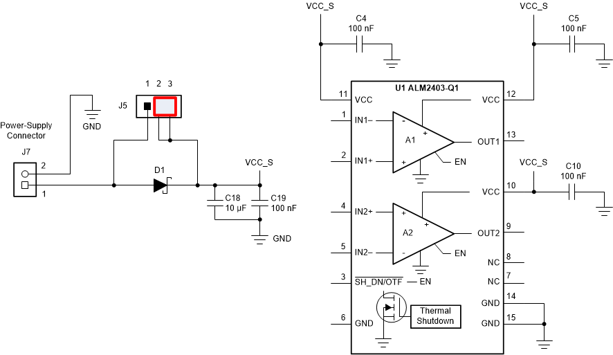
The power-supply connections for the ALM2403Q1EVM are provided through connector J7 at the top of the EVM. Table 4-1 summarizes the pin definition for supply connector J7, and the allowed voltage range for each supply connection.
| Pin Number | Supply Connection | Voltage Range |
|---|---|---|
| J7.1 | Input stage supply (VCC) | 5 V to 24 V |
| J7.2 | Ground | 0 V |
The ALM2403Q1 is configured to use a single supply connected through J7.1 (VCC) and J7.2 (GND). By default, jumper J5 is set to shunt pins 2-3 placing a Schottky diode (D1) in series with the power supply connection. The Schottky diode blocks any reverse current into the VCC_S supply during a fault condition when the output of the amplifier is shorted to a higher potential than the VCC_S supply. Place J5 to shunt pins 1-2 to bypass the optional diode (D1). Figure 4-1 shows the ALM2403Q1EVM voltage supply connections.
 Figure 4-1 ALM2403Q1EVM Voltage Supply Connections