SBOU246 January 2022 TMP61 , TMP61-Q1 , TMP63 , TMP63-Q1 , TMP64 , TMP64-Q1
3.3 Low-Pass Filtering in HW Versus SW
Noise can cause erroneous temperature measurements, which is why many designers choose to add an RC filter in hardware to filter out noise coming from the system. But instead of filtering in hardware, you can use this method to eliminate the need for the extra resistor and capacitor, enabling greater board and cost savings. Implementing your filter in software gives you more control over the filter's response by changing the alpha value in real time. Additionally, having the ability to set the filtered temperature minimizes your start-up time.
There are three variables needed for the firmware based low-pass filter:
Alpha
Measure Temp
Filtered Temp
Alpha: This variable controls how much noise is filtered out.
Measured Temp: This variable stores your calculated, pre-filtered temperature reading.
Filtered Temp: This variable stores the resulting temperature after having passed the temperature value through the filter.
The firmware low-pass filtering is executed by the following equation:
Low pass filter equation:
where
- Y = Filtered Temp
- α = Alpha
- X = Measured Temp
Simplifying...
Simplifying further...
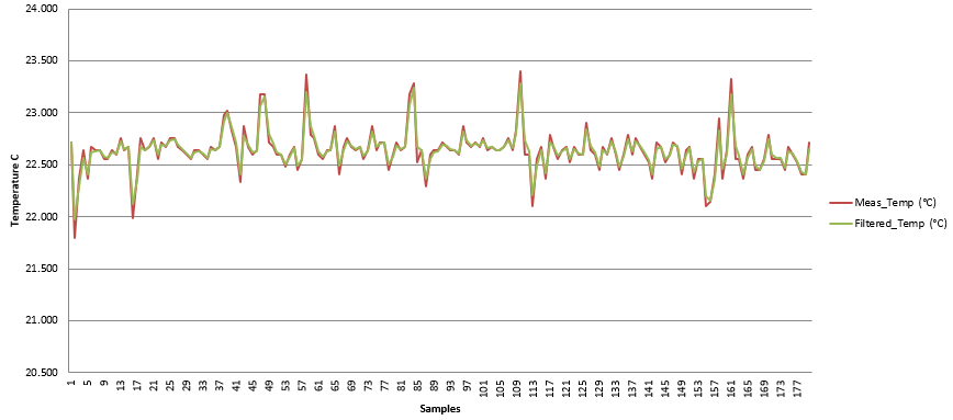
On the Low-Pass Filter tab of the Thermistor Design Tool, you can adjust the alpha and samples per second values to change the filter. In Figure 3-8, you can see that the alpha was set to 0.8. The result seen in Figure 3-9 is that the resulting temperature data after implementing the low pass filter does not change much from the raw data.
 Figure 3-8 Low-Pass Filter Setting With 0.8 Alpha Value.
  Figure 3-9 Low-Pass Filter Response With 0.8 Alpha Value.
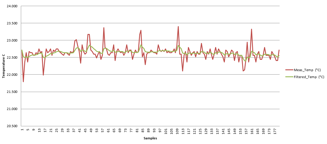
 After adjusting the alpha value, a filtered response for an alpha value of 0.2 is shown below:
 Figure 3-10 Low-Pass Filter Response With 0.2 Alpha Value.
 An example of the C code for the low pass filter from the Thermistor Design Tool can be seen in Figure 3-11.
 Figure 3-11 Low-Pass Filter Example C Code.
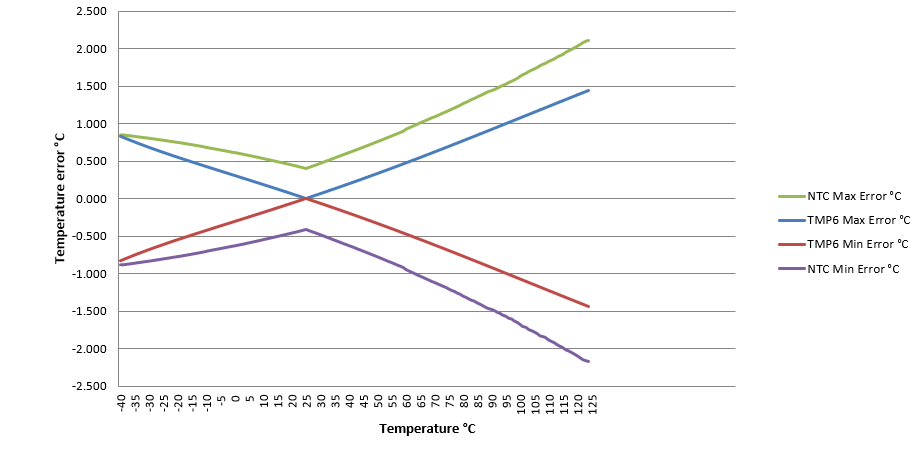
  Figure 3-12 Corrected Thermistor Accuracy Comparison.