SLAAEF5 March 2024 MSPM0G1505 , MSPM0G1505 , MSPM0G1506 , MSPM0G1506 , MSPM0G1507 , MSPM0G1507 , MSPM0L1303 , MSPM0L1303 , MSPM0L1304 , MSPM0L1304 , MSPM0L1304-Q1 , MSPM0L1304-Q1 , MSPM0L1305 , MSPM0L1305 , MSPM0L1305-Q1 , MSPM0L1305-Q1 , MSPM0L1306 , MSPM0L1306 , MSPM0L1306-Q1 , MSPM0L1306-Q1
- 1
- Abstract
- Trademarks
- 1Introduction
- 2Algorithm Introduction
- 3Gauge GUI Introduction
- 4MSPM0 Gauge Evaluation Steps
- 5MSPM0 Gauge Solutions
- 6References
2.1 Battery Basic Knowledge Introduction
The gauge algorithm is mostly used to tell users the battery working conditions, and reach a balance between outputting max capacity and extending the battery life. Here, the basic control strategy and the battery performance under these two conditions are shown.
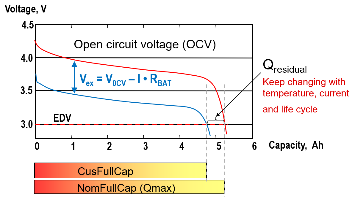
The Figure 2-1 shows a battery discharge pattern for a one-cell LiCO2 battery and the related concept we want to introduce. The red line represents the open circuit voltage (OCV), which means the potential difference between the positive electrode (PE) and the negative electrode (NE) when no current flows and the electrode potentials are at equilibrium. For OCV, it normally can be treated to equal to battery voltage after resting the battery for 1-2 hours. The Blue line means the runtime cell voltage (Vcell). As the battery has internal resistance, you will see a voltage drop between OCV and Vcell with a constant load.
For a LiCO2 battery, due to the chemical limitation, a full charge voltage threshold (like 4.2V) and an end of discharge voltage threshold (like 3V) will be set to avoid irreversible damage on the battery. That means with different discharge current, you can get different capacities from the battery. Besides, the output capacity is also influenced by the temperature, as the Rcell will get reduced while the temperature is increasing. In this gauge solution, the unchangeable capacity is called NomFullCap, which represents the movable lithium ions in the electrode structure and its quantity does not vary with temperature or C-rate of cell usage. The changeable capacity is called CusFullCap, which means the usable capacity by end users and affected by the battery running conditions and threshold setting.
 Figure 2-1 Battery Discharge
Pattern
Figure 2-1 Battery Discharge
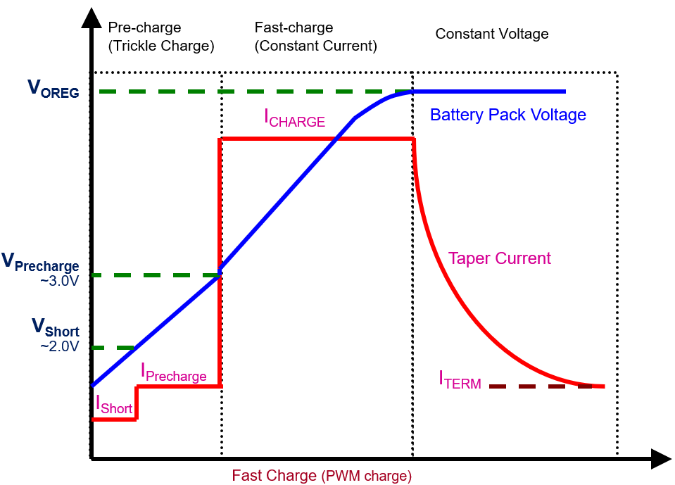
PatternThe Figure 2-2 shows a battery charge pattern for a normal one cell battery. For a charging condition, it can be simplified into a constant current (CC) window and then a constant voltage (CV) window. At the end of charge, if the charge voltage is constant, the current is reduced in an exponential order. If the current turns to 0, the NomFullCap is obtained. However, to avoid waiting for a long time, actually a terminating charge current is set, like 1/20 capacity (1/20C), which causes a little reduction on CusFullCap, compared with NomFullCap.
 Figure 2-2 Battery Charge Pattern
In a word, NomFullCap is obtained from one OCV to another OCV. CusFullCap is gotten from one Vcell to another Vcell. So NomFullCap always covers the CusFullCap.
In this gauge algorithm, the NomFullCap range is based on the per saved OCV range in the SOC-OCV table (circuitParamsTable). For the CusFullCap range, it is based on the MaxFullChgVoltThd and EmptyDhgVoltThd setting, and it also changes after self-learning. To leave some margin, it is suggested that you make the OCV range for NomFullCap to be a little larger that the voltage range for CusFullCap.