SLAAEF5 March   2024 MSPM0G1505 , MSPM0G1505 , MSPM0G1506 , MSPM0G1506 , MSPM0G1507 , MSPM0G1507 , MSPM0L1303 , MSPM0L1303 , MSPM0L1304 , MSPM0L1304 , MSPM0L1304-Q1 , MSPM0L1304-Q1 , MSPM0L1305 , MSPM0L1305 , MSPM0L1305-Q1 , MSPM0L1305-Q1 , MSPM0L1306 , MSPM0L1306 , MSPM0L1306-Q1 , MSPM0L1306-Q1


  1.   1
  2.   Abstract
  3.   Trademarks
  4. 1Introduction
  5. 2Algorithm Introduction
    1. 2.1 Battery Basic Knowledge Introduction
    2. 2.2 Different SOCs and Used Equations
      1. 2.2.1 NomAbsSoc Calculation
        1. 2.2.1.1 Coulometer With OCV Calibration
        2. 2.2.1.2 Battery Model Filter
      2. 2.2.2 CusRltSoc Calculation
      3. 2.2.3 SmoothRltSoc Calculation
    3. 2.3 Algorithm Overview
      1. 2.3.1 Voltage Gauge Introduction
      2. 2.3.2 Current Gauge Introduction
      3. 2.3.3 Capacity Learn Introduction
      4. 2.3.4 Mixing Introduction
  6. 3Gauge GUI Introduction
    1. 3.1 MCU COM Tool
    2. 3.2 SM COM Tool
    3. 3.3 Data Analysis Tool
  7. 4MSPM0 Gauge Evaluation Steps
    1. 4.1 Step1: Hardware Preparation
    2. 4.2 Step2: Get Battery Model
      1. 4.2.1 Battery Test Pattern
      2. 4.2.2 Battery Model Generation
    3. 4.3 Step3: Input Customized Configuration
    4. 4.4 Step4: Evaluation
      1. 4.4.1 Detection Data Input Mode
      2. 4.4.2 Communication Data Input Mode
  8. 5MSPM0 Gauge Solutions
    1. 5.1 MSPM0L1306 + 1 LiCO2 Battery
      1. 5.1.1 Hardware Setup Introduction
      2. 5.1.2 Software and Evaluation Introduction
      3. 5.1.3 Battery Testcases
        1. 5.1.3.1 Performance Test
        2. 5.1.3.2 Current Consumption Test
    2. 5.2 MSPM0G3507 + BQ76952 + 4 LiFePO4 Batteries
      1. 5.2.1 Hardware Setup Introduction
      2. 5.2.2 Software and Evaluation Introduction
      3. 5.2.3 Battery Testcases
        1. 5.2.3.1 Performance Test1 (Pulse Discharge)
        2. 5.2.3.2 Performance Test2 (Load Change)
  9. 6References

Detection Data Input Mode

In this mode, you need the MSPM0 Gauge board and a real battery for test. The detection data (Vcell, Icell, Tcell) comes from the real detected signals. The GUI can help to record the battery running data for further analysis.

For software setting, you need to download the gauge code to the launchpad after changing the detection mode to "DETECTION_DATA_INPUT" in "Gauge_UserConfig.h".
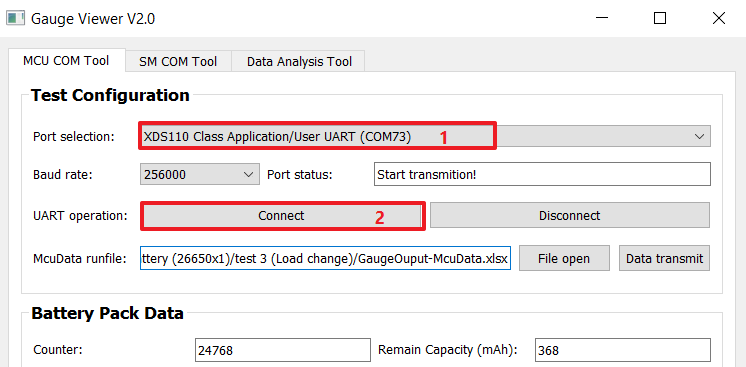
GUID-C0F119E8-466E-482D-8718-7DBE3D85184A-low.pngFigure 4-11 Detection Data Input Mode

For GUI control, you only need to select the right port with the name XDS110 Class Application/User UART and then click the connect button. If the MCU already works, you will see the test data at MCU Test Data block. After you click the disconnect button, the data will be saved in excel type under the same address of GUI, with the name "YYYY-MM-DD-HH-MM-McuData.xlsx".