SLAAEF9 November 2023 MSPM0L1306
- 1
- Abstract
- Trademarks
- 1MSPM0 Portfolio Overview
-
2Ecosystem And Migration
- 2.1 Ecosystem Comparison
- 2.2 Migration Process
- 2.3 Example
- 3Core Architecture Comparison
- 4Digital Peripheral Comparison
- 5Analog Peripheral Comparison
2.3 Example
The MSPM0 design flow is shown below. This example aims to use PWM to drive LED.
- Choose the right MSPM0 MCU and select hardware and order an EVM, here we use Launchpad MSPM0L1306.
- Set up CCS and SDK, detail can be seen in Section 2.2.
- Code import.
When the environment is ready, you can import code into CCS. As for this example, a timer is used to control PWM. The first thing to do is understand any differences between the timer modules between RL78 and MSPM0, and choose the similar example in SDK.
The closet example in the SDK is probably ” timx_timer_mode_pwm_center_stop”. Once a similar example is found, open CCS and import the code example by going to Project --> Import CCS Projects... and navigate it to the MSPM0 SDK example folder.
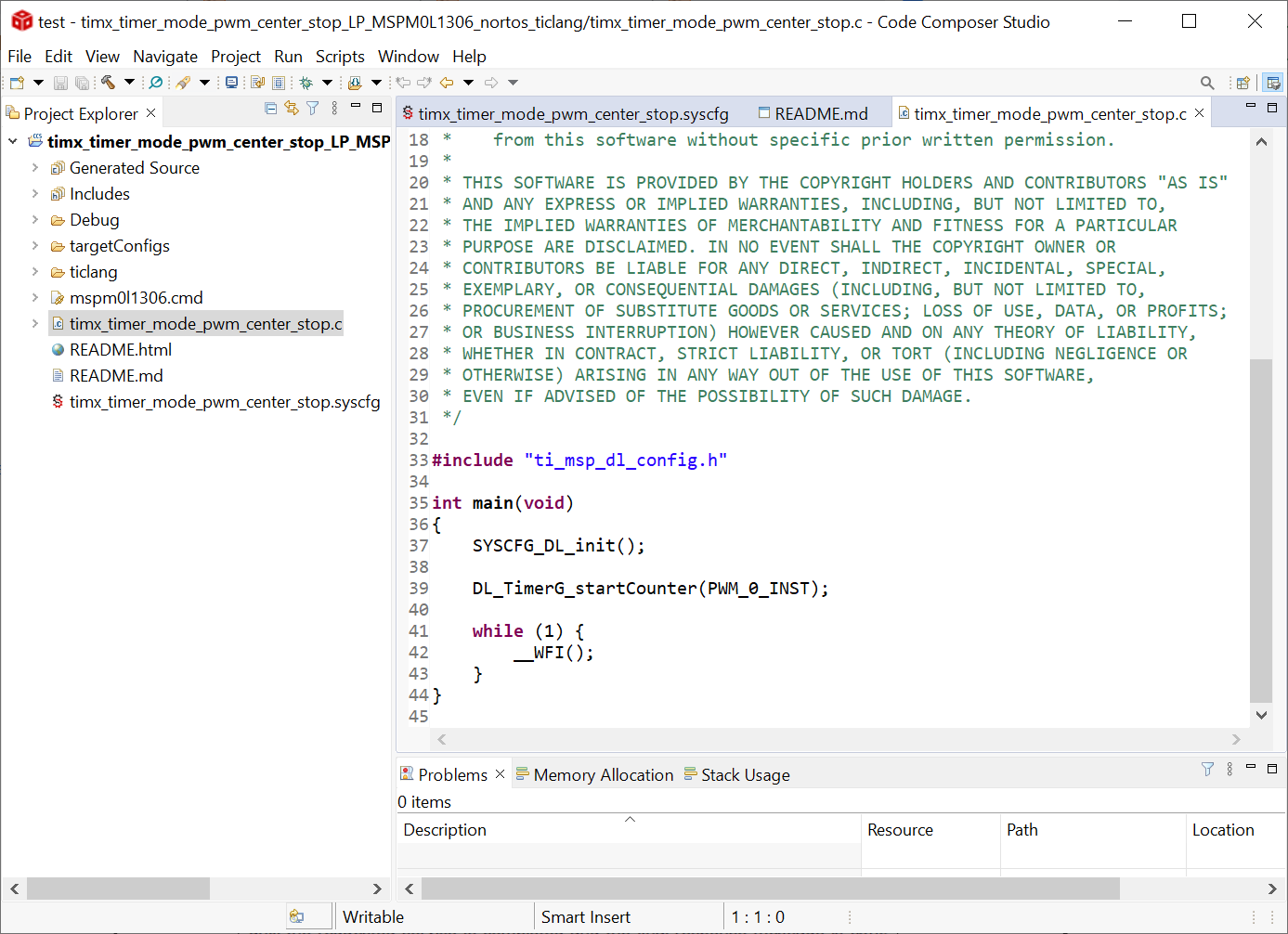 Figure 2-44 Code Example File
 - Modify
project.
To see the SysConfig configuration, open the .syscfg file. Select TIMER-PWM section to generate PWM, as shown in Figure 2-45. Check the PWM’s clock configuration, like self frequency and duty cycle. In this case, PWM frequency is 2.7Hz and 75% duty cycle. You can change duty cycle easily through typing 50% in desired duty cycle, and then Counter compare Value changes automatically.
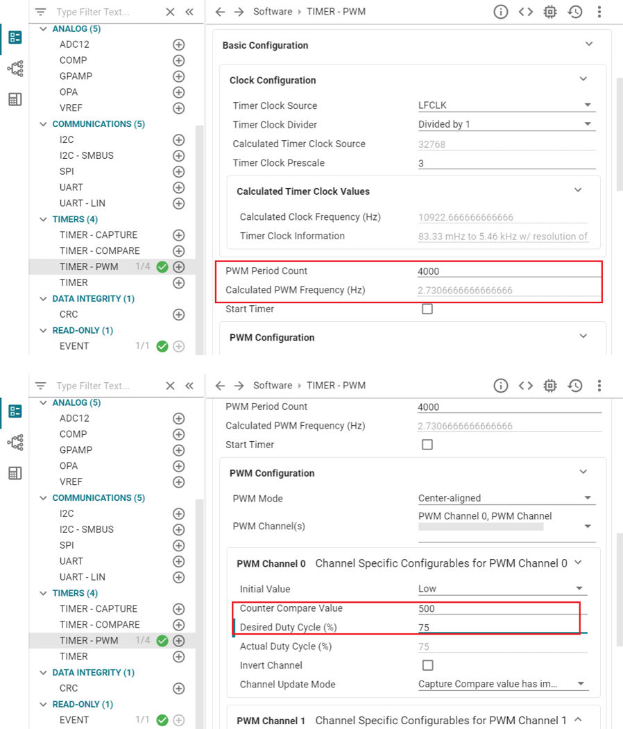 Figure 2-45 PWM Configuration in
SysConfig
Figure 2-45 PWM Configuration in
SysConfigTo further elaborate on each feature module, you can click “?” next to each item.
 Figure 2-46 To Get Detailed Information of
Each Item
Figure 2-46 To Get Detailed Information of
Each ItemAlso check the rest feature of TIMER-POWER module and pins being used by clicking the chip icon in the top right and checking the highlighted pins for the PWM.
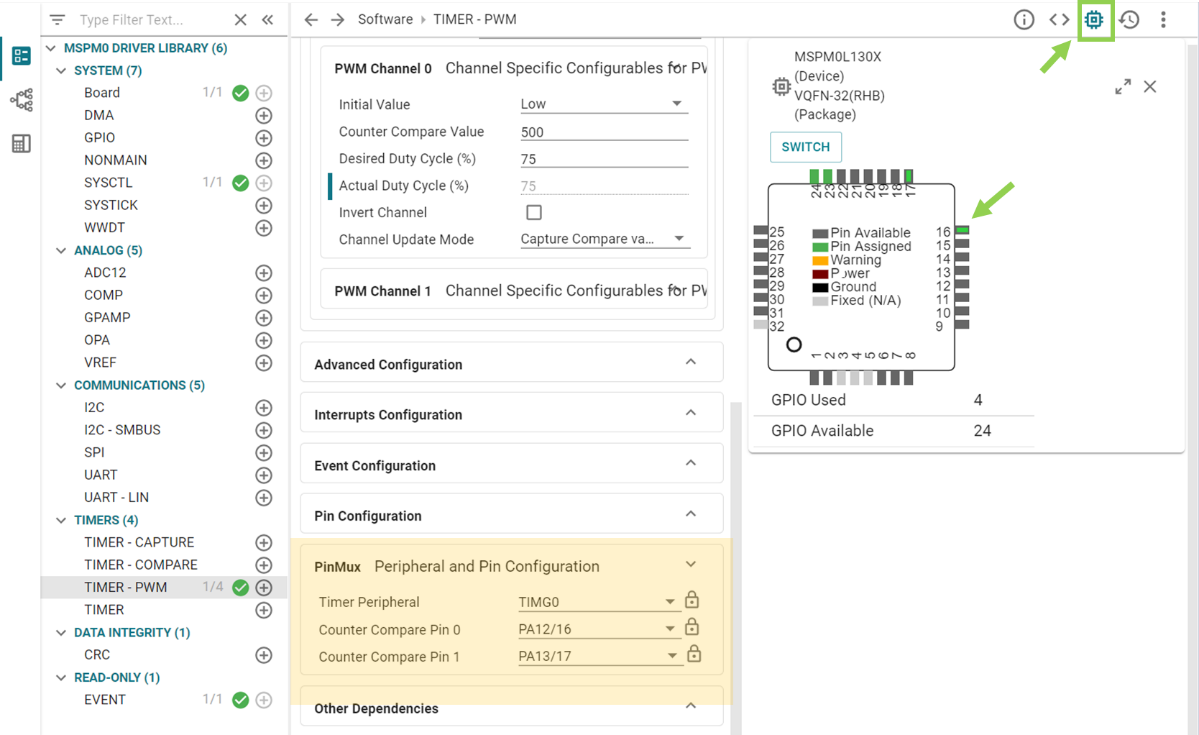 Figure 2-47 Pins Configuration
When the project is saved and rebuilt, SysConfig updates the files in Figure 2-48. At this point, the example hardware configuration has been modified to match the full functionality of the original software being ported.
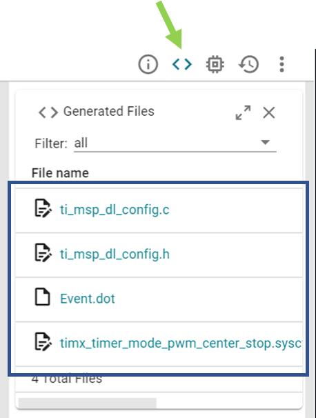 Figure 2-48 The files SysConfig
Updates
Figure 2-48 The files SysConfig
UpdatesThe only remaining effort is to check application-level software. This example generates PWM waves like SDK code, so there is no need to change the .c file.
- Hardware
setup.
Get LaunchPad plugged into the computer. According to pins configurations, use DuPont cables to connect the PA12 to the LED pins.
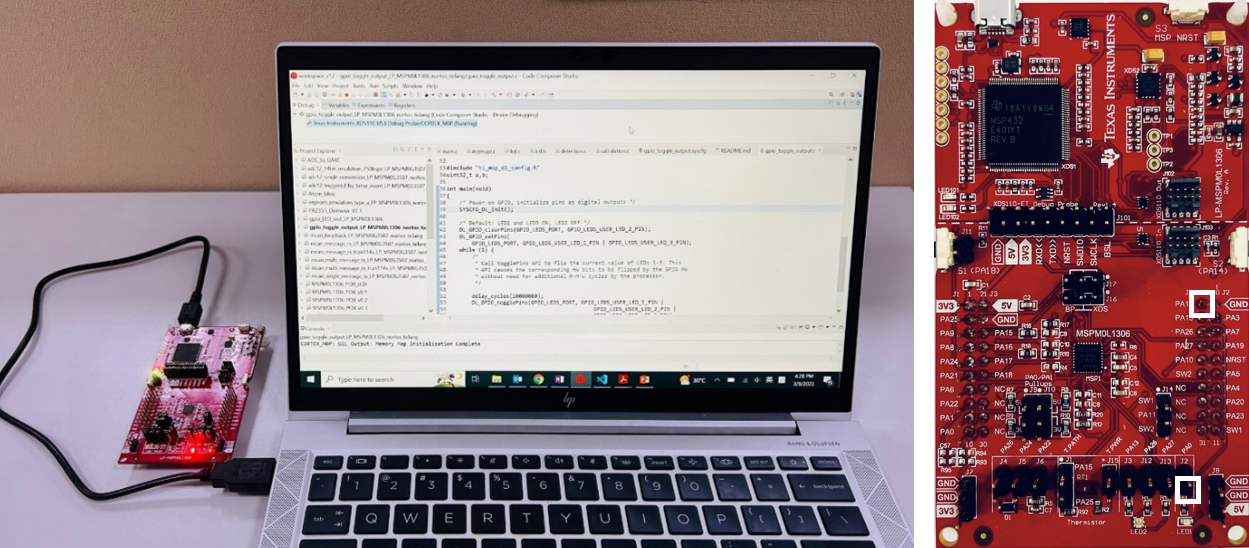 Figure 2-49 Hardware Setup
 - Debug and verify.
Start debug, by clicking debug icon. And you can set breakpoint by double-click the space before the line number or adding one line code __BKPT();
 Figure 2-50 Add Breakpoint Solutions
Try to use debug functions (detailed can be seen in Section 2.2.2.2) and verify the feasibility of the procedure. While debugging, LED can be toggled as code is running step by step.
- Generate PCB library and import to Altium
Design.
The specific steps are shown in Figure 2-51. Go to the entrance of Ultra Librarian tool under MSPM0 device page (detailed can be seen in Section 2.2.5). Clink View options. Select your wanted CAD format and Pin ordering, then you can get the Altium design lib file.
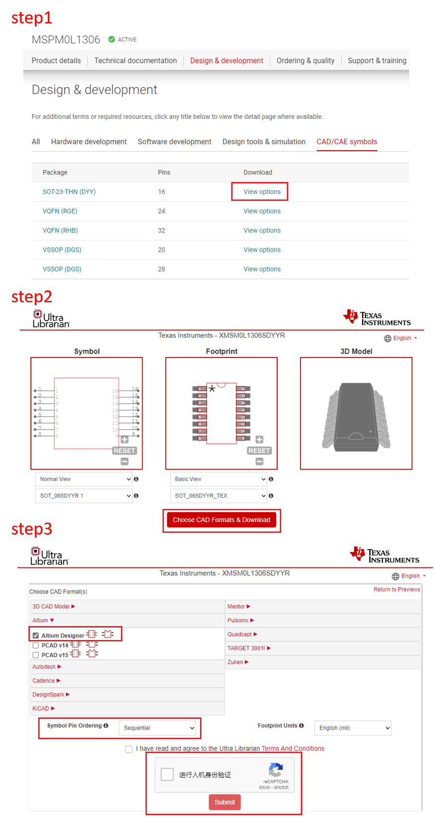 Figure 2-51 Ultra Librarian Tool
Download
Figure 2-51 Ultra Librarian Tool
DownloadAs the lib have been downloaded, the next step is to run Altium Designer script and generate PCB lib and schematic library, as shown in Figure 2-52.
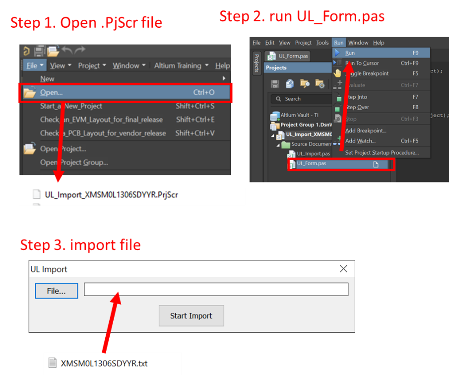 Figure 2-52 Run Altium Designer Script
After completing the steps, the following new files are going to generated in the same source folder.
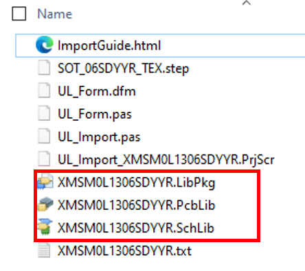 Figure 2-53 PCB Library and Schematic
File
Figure 2-53 PCB Library and Schematic
FileThe final step is to import them into your AD lib, as shown in Figure 2-54. And based on this, a schematic and PCB can be designed.
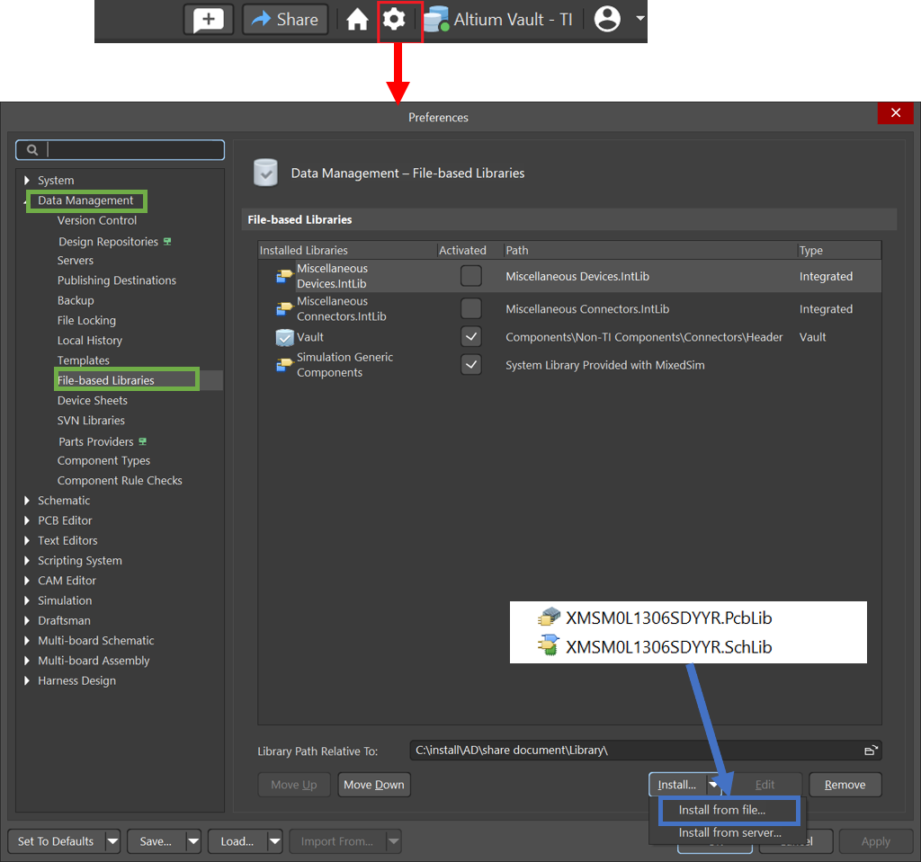 Figure 2-54 Import library
 - Design in MSPM0.
- Mass production.