SLUAAF8 October 2021 BQ24707 , BQ24707A , BQ24725A , BQ24735 , BQ24770 , BQ24780S , BQ24800 , BQ25700A , BQ25708 , BQ25710 , BQ25720 , BQ25730 , BQ28Z610-R1 , BQ4050 , BQ40Z50 , BQ40Z50-R1 , BQ40Z50-R2 , BQ40Z80
2.1 Gauge Setup
For the tests in this application note, the gauges were calibrated following the guidelines in the Technical Reference Manual (TRM) of the respective gauge. A Relax Discharge Relax (RDR) cycle was performed on the batteries to gather data which was submitted to the Gauge Parameter Calculator Chemistry ID tool (GPCCHEM)(5) to find the corresponding chemistry ID. Finally, a learning cycle was run on the batteries to complete the gauge setup(6). After these steps are finished, the application-specific functions can be enabled, like LED SOC display formatting, protection thresholds, and charging profiles in the Advanced Charge Algorithm section(7).
The final golden image can be exported from the gauge and uploaded to new gauges during production after the gauge setup is completed. Only one learning cycle is required. Voltage and current calibration can be performed on several gauges and the values can be averaged for the final golden image if the variations are low between packs.
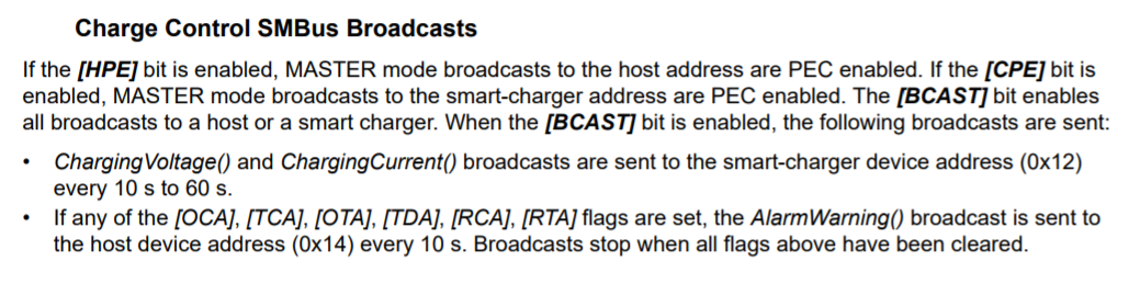
More of the broadcast information is found in the gauge's TRM:
After the initial setup, place the gauge thermistor as close as possible to the battery to get the most accurate temperature reading during battery cycling. The gauge thermistor is the only thermistor needed, the charger thermistor is not necessary.
Following the specifications from the battery manufacturer, the Advanced Charging Algorithm section of dataflash can be setup to match the battery and application-specific needs. Usually in the Constant Current (CC) mode the charge current is higher in the medium to high voltage ranges, compared to the low or precharge voltage range. During cold temperatures the charge current can be reduced, and in hot temperatures the final charge voltage can be reduced to increase the battery longevity. Further explanations are found in Section A.
With R2 or newer firmware on the BQ40Z50, the charge current and charge voltage can also be reduced depending on the cell degradation. The degradation thresholds can be based on either State of Health (SOH) or cycle count. This feature is helpful for battery safety and longevity.
Many of the charging parameters that can be modified using the Advanced Charge Algorithm settings in the TI battery gauges. The precharge, low voltage, medium voltage, and high voltage thresholds are all adjustable as well. T1–T6 indicate the temperature range thresholds that can also be modified following the Advanced Charge Algorithm application report.
 Figure 2-1 Charging Profile Using
Advanced Charging Algorithm
Figure 2-1 Charging Profile Using
Advanced Charging Algorithm