SLUUCU7 November   2023 BQ25960H


  1.   1
  2.   Description
  3.   Get Started
  4.   Features
  5.   Applications
  6.   6
  7. 1Evaluation Module Overview
    1. 1.1 Introduction
    2. 1.2 Kit Contents
    3. 1.3 Specification
    4. 1.4 Device Information
  8. 2Hardware
    1. 2.1 Equipment
    2. 2.2 Equipment Setup
    3. 2.3 I/O Descriptions
  9. 3Software
    1. 3.1 Software Setup
  10. 4Implementation Results
    1. 4.1 Test Procedure
      1. 4.1.1 Initial Settings
      2. 4.1.2 Communication Verification
      3. 4.1.3 Switched Cap Mode Charge Verification
      4. 4.1.4 Bypass Mode Charge Verification
      5. 4.1.5 Dual BQ25960H Operation
      6. 4.1.6 BQ25611D Charge Verification
  11. 5Hardware Design Files
    1. 5.1 Schematic
    2. 5.2 PCB Layout Guidelines
      1. 5.2.1 Board Layout
    3. 5.3 Bill of Materials
  12. 6Additional Information
    1.     Trademarks

Bypass Mode Charge Verification

Use the following steps to verify battery charging in bypass mode.

  1. Make sure the steps in Section 4.1.1 and Section 4.1.2 have been followed.
  2. Set PS1 to 4.1 V. Load #1 can be kept at 4.0 V.
  3. Make sure the "Enable Charge" box is not selected. Then, click "Enable Bypass Mode".
    GUID-20210405-CA0I-WQK1-W5BL-LQZ1FXJQSB9W-low.png

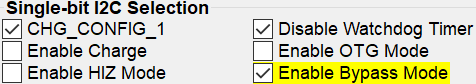
  4. Click Enable Charge. After enabling charge, the output current flowing into Load #1 is approximately equal to the input current flowing out of PS1.
  5. Change the charge current:
    By increasing the input voltage, the output current increases together with the input current. The output current is always approximately equal to the input current.
  6. To stop charging, deselect the Enable Charge box. The input current and the output current both fall to zero.