SLVAFH1A December 2022 – December 2023 TPS62933 , TPS62933F , TPS62933O , TPS62933P
- 1
- Create an Inverting Power Supply Using a TPS6293x Buck Converter With Internal Compensation
- Trademarks
- 1Configuring the Buck Converter for Inverting Buck-Boost Topology Application
- 2Choosing the Correct Buck Converter for Inverting Power Application
- 3Selecting Applicable External Components for Inverting Power Application
- 4Experimental Results
- 5Summary
- 6References
- 7Revision History
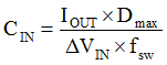
3.3 Input Capacitors
The input capacitors between VIN and ground are used to limit the voltage ripple of the input supply. Equation 12 to Equation 15 are used to estimate the capacitance, maximum ESR, and current rating for the input capacitor, CIN. Using Equation 13, the estimated average input current is 3.6 A. Considering 1% volatge ripple, using Equation 12 and Equation 14, the minimum required input capacitance is 11.25 μF, and the maximum ESR is 44.4 mΩ. Using Equation 15, the input capacitor needs at least a 2.1-A current rating. Three, 10-μF, 50-V X7R in parallel are used for the input capacitor, because of the low ESR and size.